Design optimization method for buffer structure at entrance of beveled tunnel

A buffer structure and optimization method technology, applied in design optimization/simulation, tunnels, mining equipment, etc., can solve problems such as difficult quality control, difficult construction, and labor-intensive

Active Publication Date: 2021-05-18
HEBEI UNIV OF ENG
View PDF9 Cites 2 Cited by
  • Summary
  • Abstract
  • Description
  • Claims
  • Application Information

AI Technical Summary

Problems solved by technology

However, when the trumpet-shaped buffer structure is poured, the formwork needs to be unfolded according to a certain curve or angle. The construction is difficult, the quality is difficult to control, and it is labor-intensive and inconvenient to manufacture.

Method used


Image

  • Design optimization method for buffer structure at entrance of beveled tunnel
  • Design optimization method for buffer structure at entrance of beveled tunnel
  • Design optimization method for buffer structure at entrance of beveled tunnel

Examples


Embodiment Construction

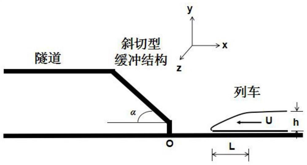
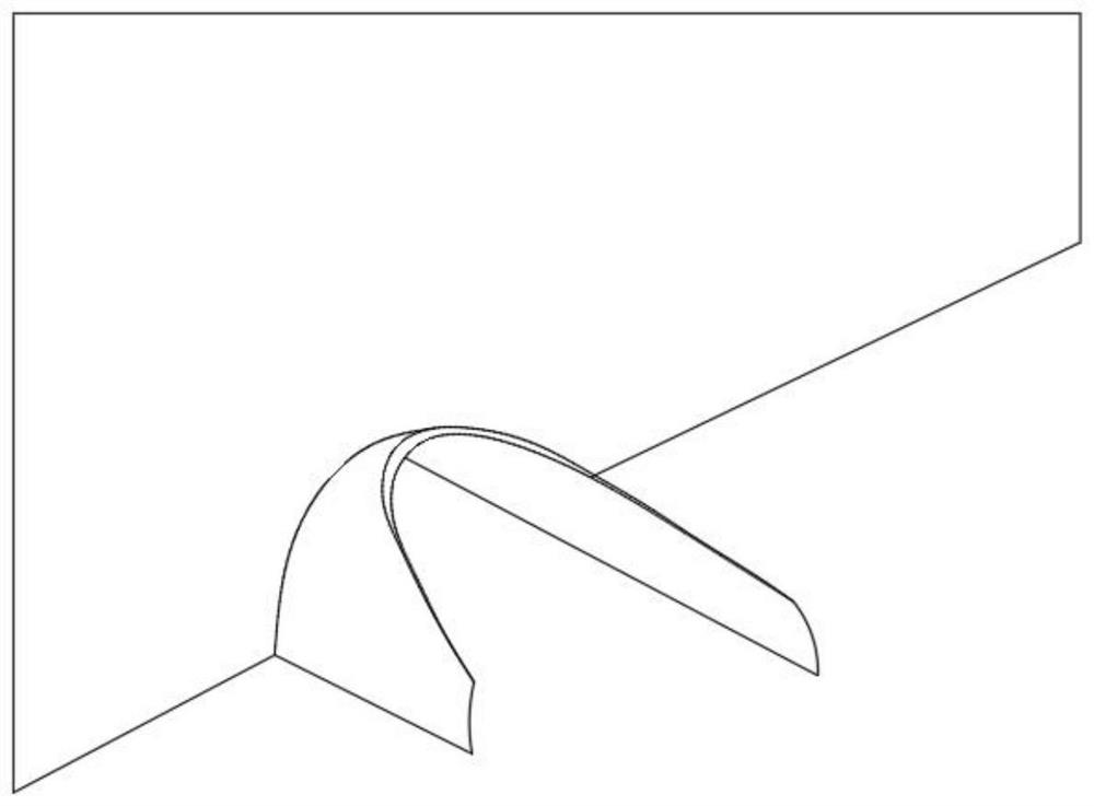
[0105] Such as image 3 with figure 1 As shown, the oblique-cut buffer structure to be designed in the present invention is obtained by cutting an oblique plane forming a certain angle with the buffer structure axis, and after cutting, it becomes a curved-edge arc-shaped structure. The beveled buffer structure is equivalent to a buffer structure provided with infinitely many curved rectangular micropores, and each micropore changes continuously. The method for designing and optimizing the above-mentioned oblique buffer structure of the present invention comprises the following steps:

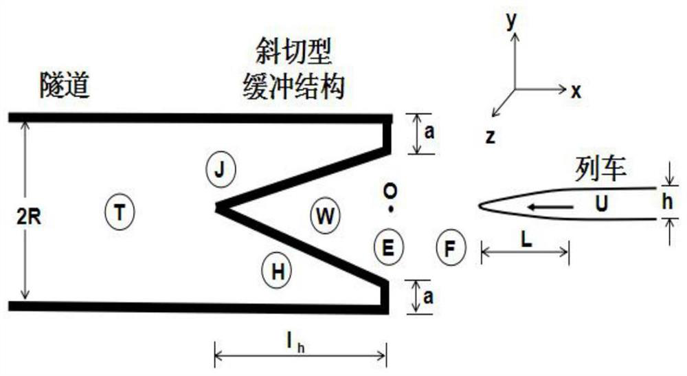
[0106] S1. Calculation model:

[0107] Such as Figure 1 to Figure 4 As shown, suppose the origin of the coordinates is at point O at the entrance of the buffer structure, the symmetry axis of the train and the tunnel coincides with the x-axis, and the train enters the tunnel at a certain speed U along the negative direction of the x-axis, assuming that the train head length L is ideally stre...


PUM


Abstract

The invention provides a design optimization method for a buffer structure at an entrance of a beveled tunnel. After the beveled buffer structure is arranged, the wavefront thickness of initial compression waves is remarkably increased, so that the rise time of the compression waves is prolonged, the pressure gradient of the initial compression waves is reduced, micro-pneumatic waves at an exit of the tunnel are relieved, and the aerodynamic effect inside and outside the tunnel can be effectively relieved. The design optimization method for the buffer structure at the entrance of the beveled tunnel specifically comprises the following steps of 1, calculating a model; 2, solving the aerodynamic effect of the tunnel based on aeroacoustics; and 3, optimizing the buffer structure. The design optimization method can be popularized and applied to the field of high-speed railway construction; the entrance of the tunnel is transformed and optimized; the structural design is scientific and reasonable; and the design optimization is accurate and easy to operate.

Description

technical field [0001] The invention belongs to the technical field of tunnel design, and in particular relates to a method for optimizing the design of an oblique-cut tunnel entrance buffer structure. Background technique [0002] Usually, when a high-speed train enters a tunnel, the front of the train compresses the air in the tunnel to form a compression wave. This compression wave propagates along the tunnel at the speed of sound, and is emitted outward through the tunnel exit in the form of micro-pressure waves. Since micro-pressure waves cause impulsive noise and low-frequency vibrations to surrounding private houses, it is very important to reduce aerodynamic effects when designing high-speed railway tunnel entrances. [0003] Aiming at the aerodynamic effect of high-speed railway tunnels, a buffer structure is usually set at the tunnel entrance, and the horn-shaped buffer structure has the best buffer effect. However, during the pouring construction of the horn-sha...

Claims


Application Information

Patent Timeline
Patent Type & Authority Applications(China)
IPC IPC(8): E21D9/14E21F17/00G06F30/20
CPCE21D9/14E21F17/00G06F30/20Y02T90/00
Inventor 闫亚光赵亚军张童童张立功赵志超周海波张晓明
Owner HEBEI UNIV OF ENG
Why Eureka
Try Eureka