Heatsink and cooling apparatus

A heat-absorbing device and heat-generating body technology, applied in lighting devices, cooling/heating devices of lighting devices, cooling/ventilation/heating transformation, etc., can solve problems such as noise, inability to cool LED lighting appliances with forced convection cooling devices, etc. To achieve the effect of increasing the flow rate

Inactive Publication Date: 2009-01-07
TE CONNECTIVITY GERMANY GMBH
View PDF1 Cites 3 Cited by
  • Summary
  • Abstract
  • Description
  • Claims
  • Application Information

AI Technical Summary

Problems solved by technology

[0014] However, in such Figure 10 In the forced convection cooling device such as the cooling device 101 shown, there are problems such as noise due to the use of a blower, and such a forced convection cooling device cannot be used for cooling LED lighting fixtures in reality.

Method used


Image

  • Heatsink and cooling apparatus
  • Heatsink and cooling apparatus
  • Heatsink and cooling apparatus

Examples


Embodiment Construction

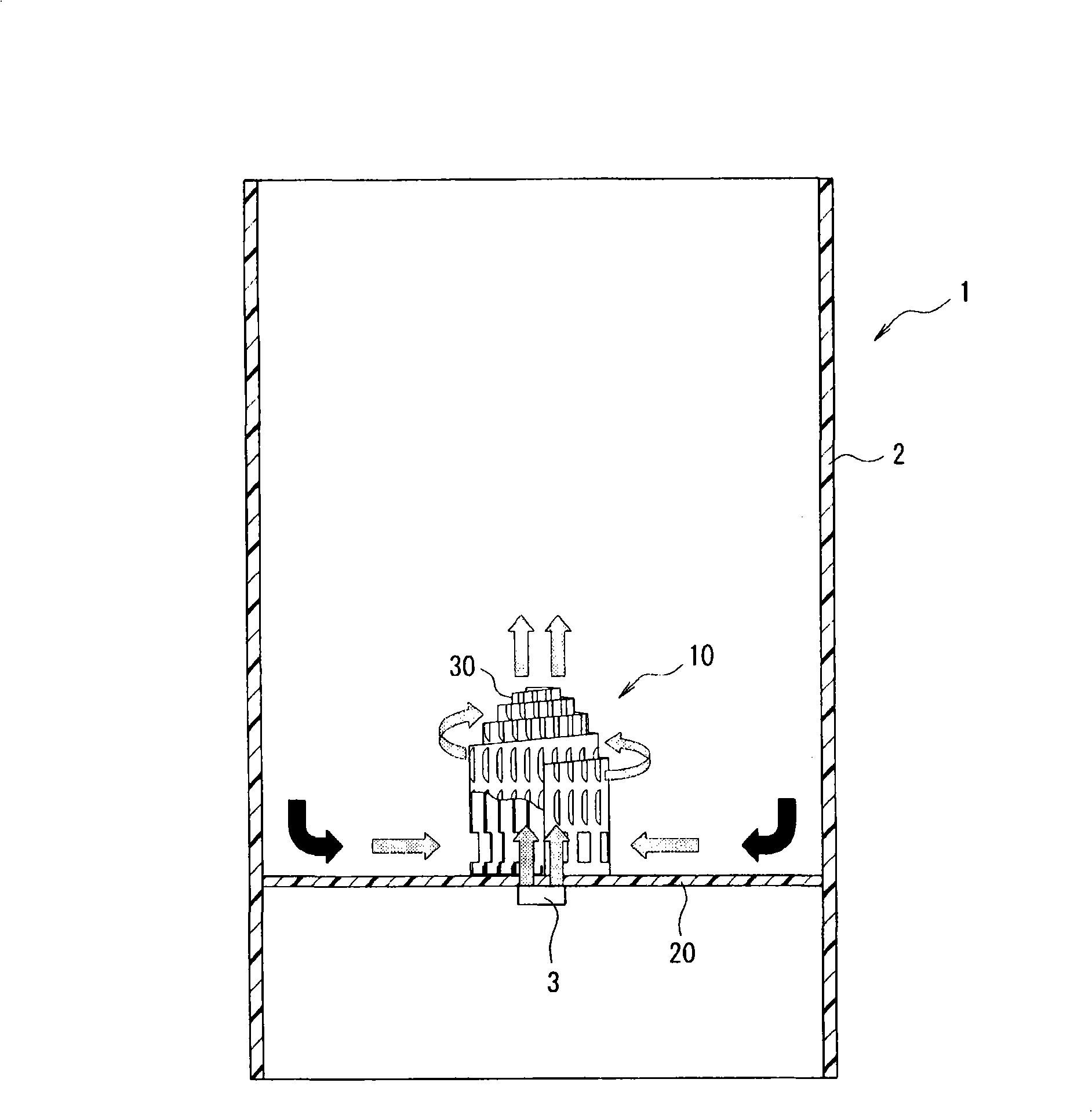
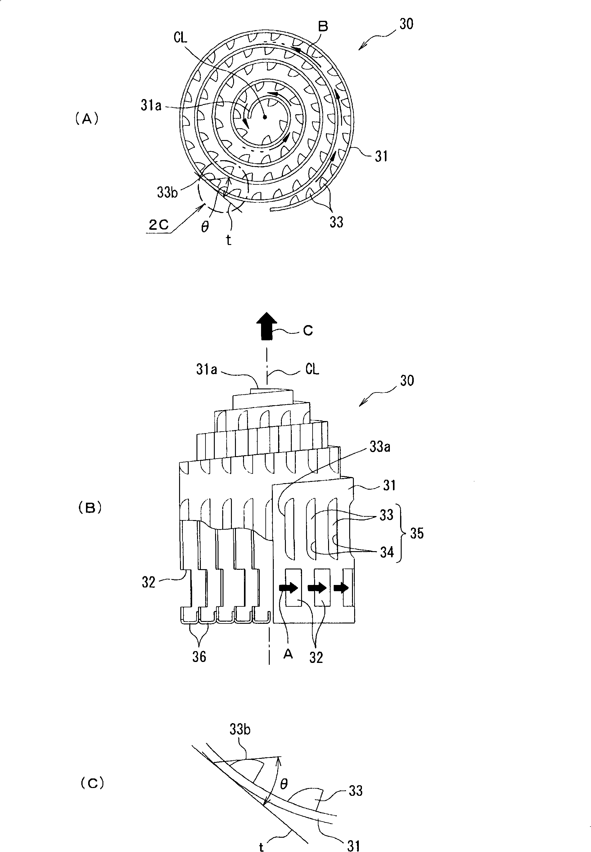
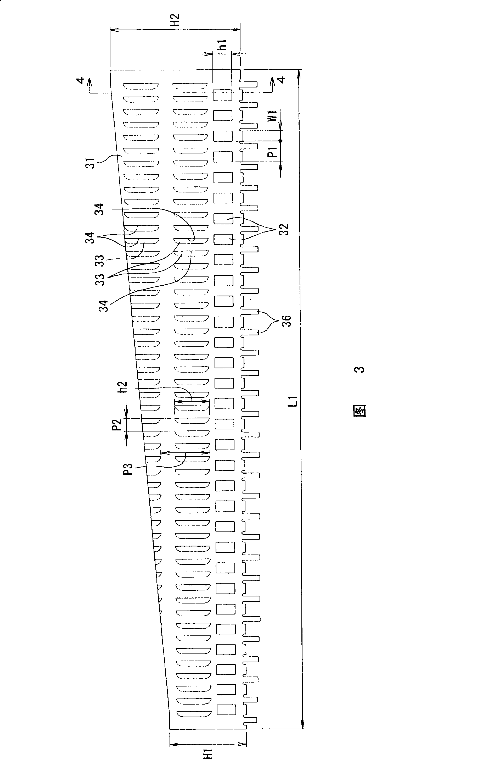
[0044] Hereinafter, embodiments of the present invention will be described with reference to the drawings. figure 1 It is a schematic cross-sectional view showing a state in which the heat absorbing device according to the first embodiment of the present invention is attached to a lighting fixture. figure 2 express figure 1 (A) is a top view, (B) is a front view with a part cut off, and (C) is an enlarged view of a part indicated by an arrow 2C in (A). Figure 3 is to constitute the figure 2 A top view of the expanded state of the metal sheet of the heat sink. Figure 4 It is a cross-sectional view taken along line 4-4 in FIG. 3 .

[0045] figure 1 Among them, a printed wiring board 20 with LEDs (heating elements) 3 mounted on the lower surface is mounted in a housing 2 of a lighting fixture 1 . And the heat sink 30 for cooling the LED3 which generate|occur|produces heat is attached to the upper surface of the printed wiring board 20. As shown in FIG. The printed wir...


PUM


Abstract

The present invention provides a natural convection-type heatsink for cooling a heating element, which is suitable for an LED lighting device and has increased cooling capacity, and a cooling apparatus. The heatsink (30) for cooling a heating element (3) comprises a metal plate (31) in the form of a band rolled around a central axis (CL) to have the shape of a scroll, wherein the height of one end in the central axis direction of the scroll from the radial outside gradually increases towards the centre part (31a) in the radial direction. A plurality of through air intake openings (32) pass through the metal plate (31) and are in the end other end in the central axis direction. A cooling apparatus (10) comprises the heatsink (30), and a printed circuit board (20). The heatsink (30) is mounted on an upper surface of the printed circuit board and the heating element is mounted on an undersurface thereof, wherein the heating element (3) is located in a central position in the radial direction and opposite the heatsink (30), such that the other end in the central axis direction is located below.

Description

technical field [0001] The present invention relates to a natural convection heat sink and a cooling device for cooling a heat generating body, and more particularly to a natural convection heat sink and a cooling device suitable for cooling LEDs used as a light source for illumination . Background technique [0002] Conventionally, as a cooling device for cooling a heating element, a forced convection type cooling device having a relatively large cooling capacity has been widely used. The forced convection type cooling device refers to a cooling device having a structure in which a blower is added to a heat absorbing device. Conventionally, as this forced convection cooling device, for example, known Figure 10 The device shown (refer to Patent Document 1). Figure 10 It is a schematic perspective view of the state which removed the blower from the conventional cooling device. [0003] Figure 10 The cooling device 101 shown is composed of a heat sink 110 and a blower 120...

Claims


Application Information

Patent Timeline
Patent Type & Authority Applications(China)
IPC IPC(8): F21V29/00H01L23/36F21Y101/02H01L33/64
CPCH01L2924/0002H01L23/467H01L2924/00H05K7/20
Inventor 铃木满
Owner TE CONNECTIVITY GERMANY GMBH
Why Eureka
Try Eureka