Modeling method for non-axisymmetric end wall of axial flow impeller
A non-axisymmetric, axial flow impeller technology, applied in the non-axisymmetric end wall modeling of the impeller, and the modeling field of the non-axisymmetric end wall of the axial flow impeller
- Summary
- Abstract
- Description
- Claims
- Application Information
AI Technical Summary
Problems solved by technology
Method used
Image
Examples
Embodiment 1
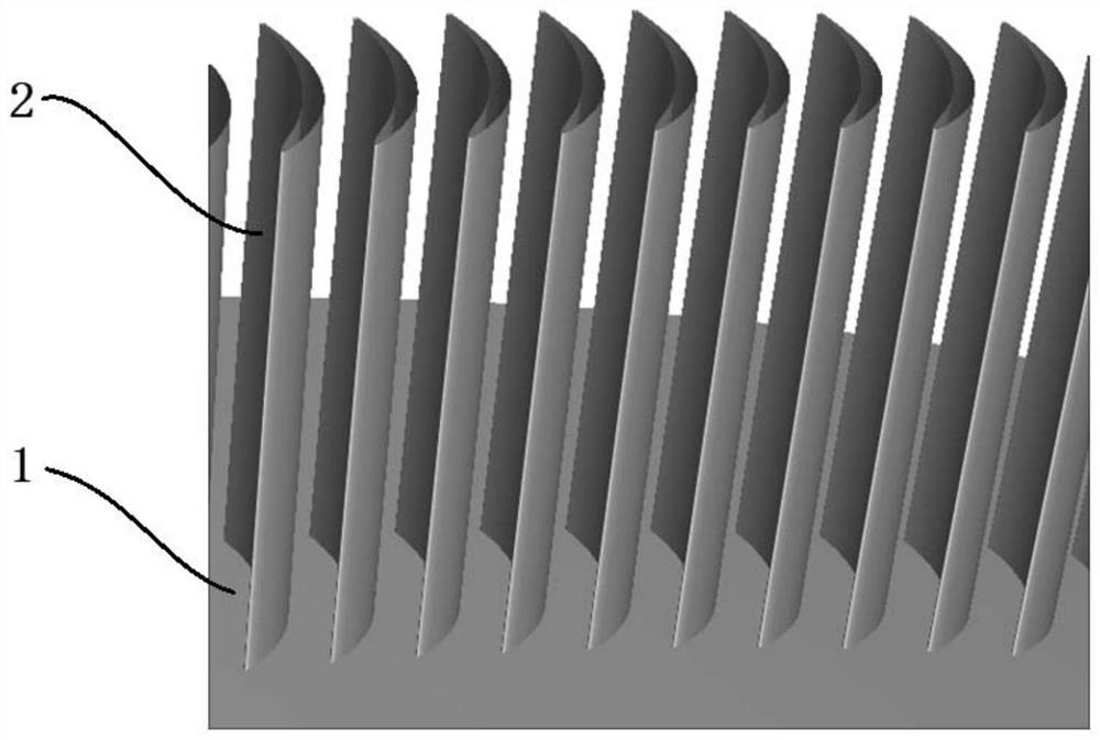
[0043] For a typical non-axisymmetric end wall structure that is concave near the suction surface and protrudes near the pressure surface, follow the steps below:
[0044] Step 1: In such as figure 1 In the molding channel of an axisymmetric end wall 1 shown, the end wall area is divided into several axial sub-areas. For example, the peripheral control lines of -20%, 0%, 20%, 40%, 60%, 80%, 100%, and 120% Cax enclose the modeling area of the non-axisymmetric end wall, where 0% Cax means that the blade front Edge in the axial position, 100%Cax represents the position of the blade trailing edge in the axial direction. The circumferential control line adopts the third-order Fourier series curve.
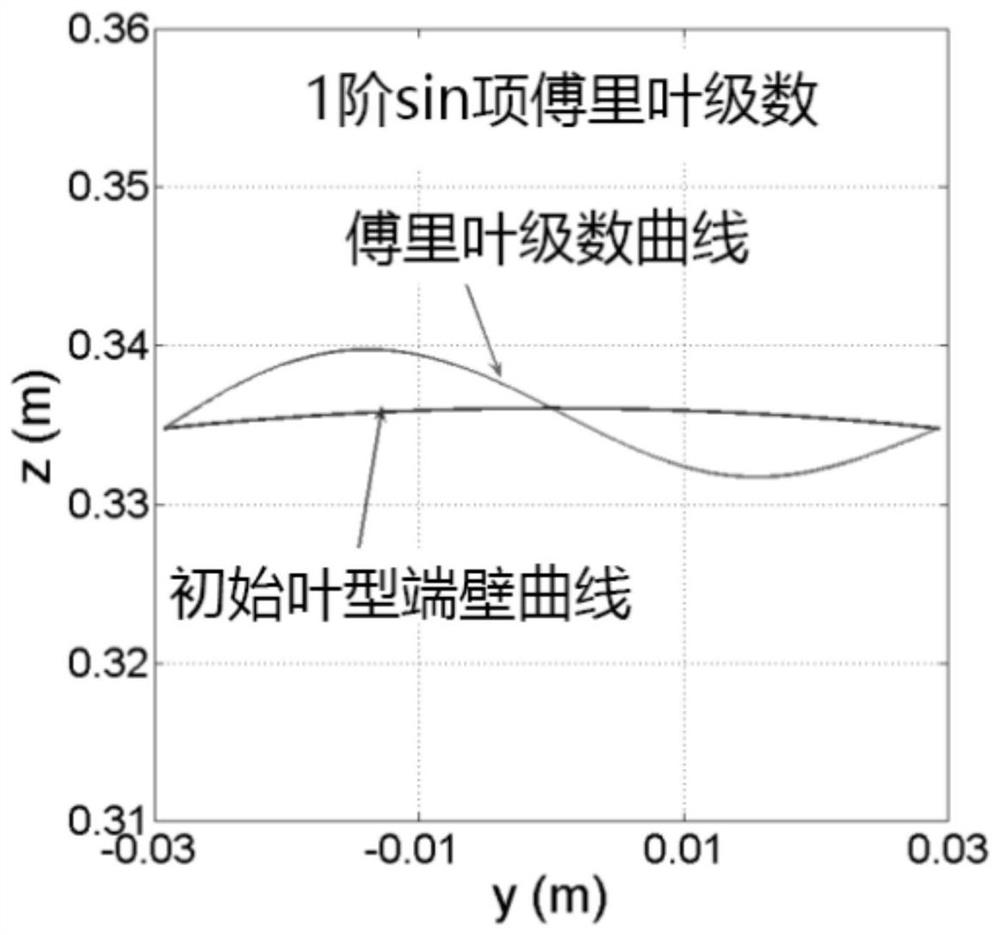
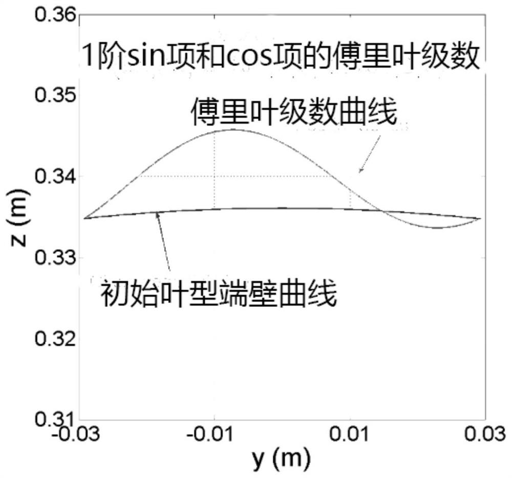
[0045] Step 2: The different axial positions of the end wall of the compressor impeller in step 1 are respectively used to construct a third-order Fourier series curve, and the starting point of the Fourier series curve is located on the suction surface of the blade. The Fourier se...
PUM
 Abstract
Description
Claims
Application Information
 - R&D
- Intellectual Property
- Life Sciences
- Materials
- Tech Scout
- Unparalleled Data Quality
- Higher Quality Content
- 60% Fewer Hallucinations
Browse by: Latest US Patents, China's latest patents, Technical Efficacy Thesaurus, Application Domain, Technology Topic, Popular Technical Reports.
© 2025 PatSnap. All rights reserved.Legal|Privacy policy|Modern Slavery Act Transparency Statement|Sitemap|About US| Contact US: help@patsnap.com


