Restraining of battery cells by way of a cambered design of the battery housing

a battery cell and cambered technology, applied in the direction of cell components, final product manufacturing, sustainable manufacturing/processing, etc., can solve the problems of reducing the lifespan of batteries, etc., to achieve the effect of preventing damage to the cambered battery cells

Active Publication Date: 2015-07-30
ROBERT BOSCH GMBH
View PDF9 Cites 37 Cited by
  • Summary
  • Abstract
  • Description
  • Claims
  • Application Information

AI Technical Summary

Benefits of technology

[0028]The elastic plates here are in each case disposed on the outermost battery cell, for example outside on the right and outside on the left, such that an elastic material is present between the respective battery cell and the end plate of the module housing when the battery cells are disposed in the module housing. The el...

Problems solved by technology

Furthermore, restraining contributes to...

Method used


Image

  • Restraining of battery cells by way of a cambered design of the battery housing
  • Restraining of battery cells by way of a cambered design of the battery housing
  • Restraining of battery cells by way of a cambered design of the battery housing

Examples


Embodiment Construction

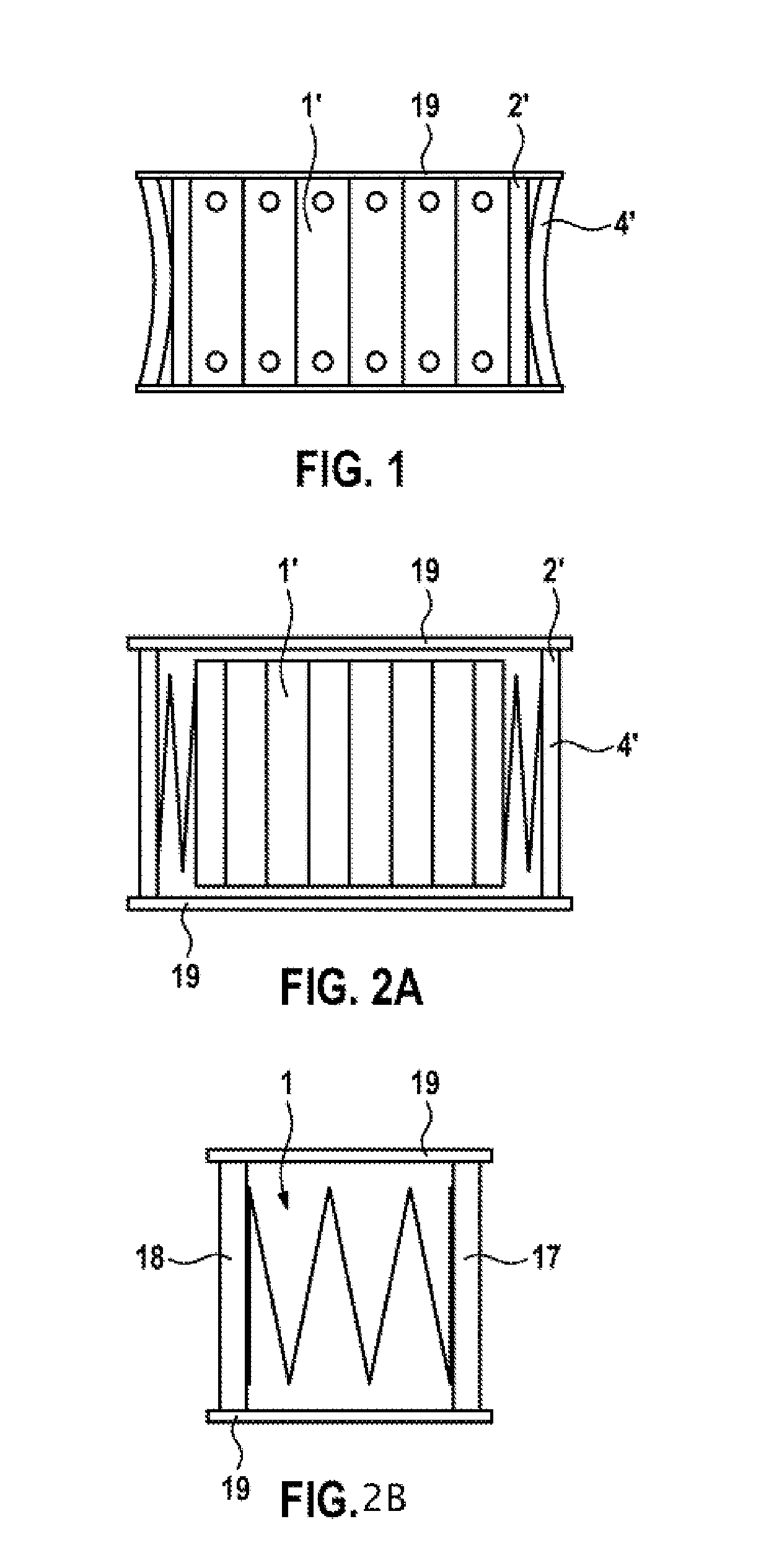
[0040]In FIG. 1, a plan view onto a known prestressed battery module is illustrated. Known battery cells 1′ here are implemented so as to be cuboid. The battery cells 1′ are placed beside one another. To the right and left of the outer battery cell 1′, spring plates 4′ which act in a similar manner to leaf springs are provided. In order to achieve a uniform distribution of pressure on the battery cells 1′, pressure distribution plates 2′, made of steel, are placed in between the spring plates 4′ and the battery cells 1′. The spring plates 4′ are compressed up to a specific pre-tension force. In order to maintain the tension, the spring plates 4′ are welded or screwed to so-called pull plates 19. The mass of a component having a spring plate 4′ and a pressure distribution plate 2′ may be approx. 300 g. For example, if eight individual battery modules are combined to form one battery pack, this amounts to a mass of 4.8 kg which is allocated to the pressure distribution plates 2′ and t...


PUM


Abstract

The invention relates to a battery cell (1) for pre-stressed battery modules (13). The invention further relates to corresponding pre-stressed battery modules (13) and corresponding production methods. The battery cell (1) has a cell housing (3) and a chemicals carrier (9). The chemicals carrier (9) is arranged in the cell housing (3). The cell housing (3) has a bulging design.

Description

BACKGROUND OF THE INVENTION[0001]Batteries are employed in many sectors of technology. A plurality of individual batteries may be combined so as to form a module. A plurality of modules may furthermore be joined together so as to form a so-called battery pack. High-performance batteries, for example high-voltage batteries, are created in this manner.[0002]The battery cells are usually implemented so as to be rectangular or cuboid. In order to ensure improved manageability and in order to provide as large an amount of energy as possible in as small a volume as possible, the rectangular battery cells are restrained or prestressed so as to form modules. Furthermore, restraining contributes to an increase in the lifespan of the batteries.[0003]In order to restrain or prestress the batteries in relation to one another, an elastic element is required here in the chain of the distribution of forces, for example in order to compensate for tolerances of the individual battery cells or of the...

Claims


Application Information

Patent Timeline
IPC IPC(8): H01M10/04H01M2/16H01M2/10B60L50/64
CPCH01M10/0481H01M2/1653H01M2/16H01M2/1016H01M50/242H01M50/417H01M50/209B60L50/64H01M50/103H01M50/249Y10T29/49108Y10T29/4911Y10T29/49115Y02E60/10Y02P70/50Y02T10/70
Inventor DEPONTE, RENEFEIGL, MARKUSEICHENDORF, ANDREASGERUNDT, OLIVER
Owner ROBERT BOSCH GMBH
Why Eureka
Try Eureka