Disk Brake

a technology for disc brakes and brakes, applied in the direction of brake elements, brake members, slack adjusters, etc., can solve the problems of relatively large installation space in the radial and peripheral directions of brakes, and achieve the effects of good thermal irradiation of components, low thermal stress, and loading of components

Inactive Publication Date: 2009-09-24
CONTINENTAL TEVES AG & CO OHG
View PDF10 Cites 35 Cited by
  • Summary
  • Abstract
  • Description
  • Claims
  • Application Information

AI Technical Summary

Benefits of technology

[0008]The object is achieved in that a radial wall thickness of the central support of the caliper bridge is designed in such a way that in an axial region of the brake linings a distance between the central support and a rotational axis of the brake disk is smaller than an external radius of the brake disk. This means that the wall thickness in the region where the central support projects beyond only the brake lining is greater than where the central support engages over the brake disk. The central support is therefore strengthened by the axially projected overlap of the brake disk and central support at the junction region between the caliper limb and caliper bridge. This proves very favorable since in this junction region the loading of the components, in particular due to notch stresses, is significantly greater than in the region of the brake disk. This design of the caliper bridge which is compatible with loading and optimized provides the advantage that the diameter of the brake disk can be designed in a maximum way. The structure of the caliper bridge with supports and windows permits good thermal irradiation of the components, as a result of which the thermal stress is kept low.
[0009]As a result of the fact that the main supports and the central support enclose the brake disk in a U shape in an axial direction, the brake disk is enclosed by the brake caliper in a way which, as it were, rounds it off and harmonizes stress. This leads to an optimum flow of force in the brake caliper and therefore to a high rigidity to prevent bending when the brake is actuated.
[0010]The brake linings are supported on bridge limbs in the peripheral direction and in the radial direction, wherein the bridge limbs are arranged on the main supports of the caliper bridge. In this context, an undercut is provided on at least one inlet-side bridge limb with respect to the brake lining. This comprises stops for the brake lining to bear against in the peripheral direction, and a supporting means for radially supporting the brake lining. The brake lining comprises a back plate and a friction lining, wherein the back plate has a rear region having two projections which adjoin in the peripheral direction. At least one of the projections is embodied in an L shape with a supporting face for providing radial support and two bearing faces for permitting bearing in the peripheral direction. The L-shaped projection engages in the undercut of the bridge limb. This type of bearing for a brake lining in the brake caliper is easy to fabricate and brings about a comfortable braking behavior.
[0011]In terms of the requirement of installation space in the peripheral direction it proves very favorable if the undercut is provided exclusively on the inlet side, with respect to a main rotational direction of the brake disk, for each brake lining in the brake caliper, and the back plate has an L-shaped projection exclusively on the inlet side, with the result that a flow of force of peripheral forces from the back plate into the brake caliper occurs by means of tension via a bearing face and a stop when the brake disk rotates in the main rotational direction, and occurs by means of pressure via a further stop and a further bearing face when the brake disk rotates in a direction opposed to the main rotational direction. The terms “on the inlet side and on the outlet side” are related to any existing brake lining in this context. This design of the bearing of the brake lining ensures that the guiding of the brake lining under tension results in a favorable braking behavior in terms of generation of noise and wear for forward travel of the vehicle. For less frequent reversing or for the stationary stage of the vehicle, the brake linings are loaded compressively. This effective application of the lining guiding principle under tension and under compression which is specifically matched to the requirements provides the advantage that the installation space of the brake caliper is considerably reduced in the peripheral direction of the brake disk since there is no need for any outlet-side undercut design. In addition, the double effect is obtained that the requirement of material and the requirement of working is decisively reduced both for the brake caliper and for the back plate of the brake lining. In particular in the case of fixed calipers, this concept is particularly simple and advantageous since said components are in principle made very rigid and therefore the reduced guidance of the lining which is present can be applied without disadvantages.

Problems solved by technology

Such brakes require a relatively large installation space in the radial and peripheral directions.

Method used


Image

  • Disk Brake
  • Disk Brake
  • Disk Brake

Examples


Embodiment Construction

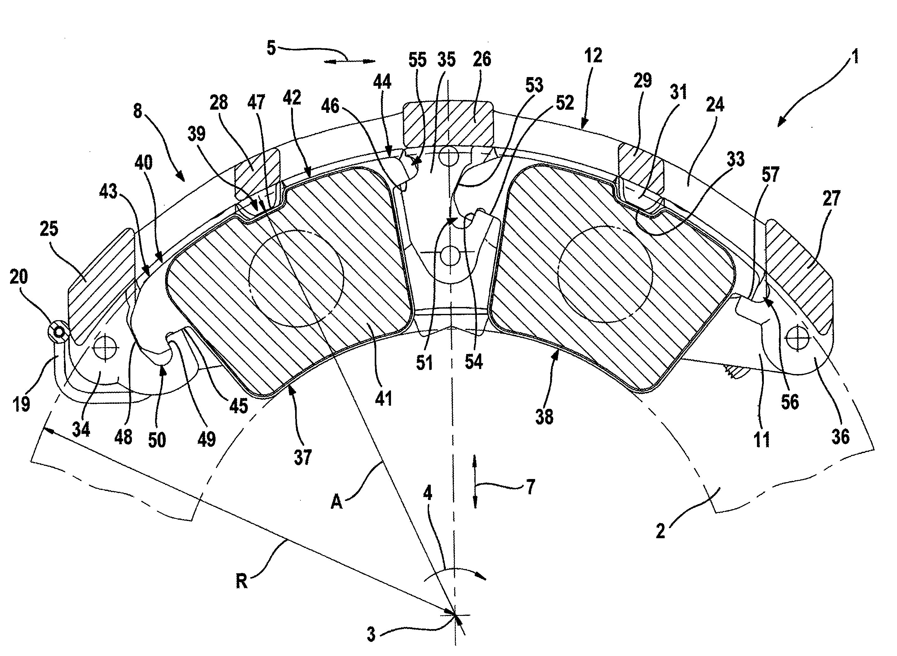
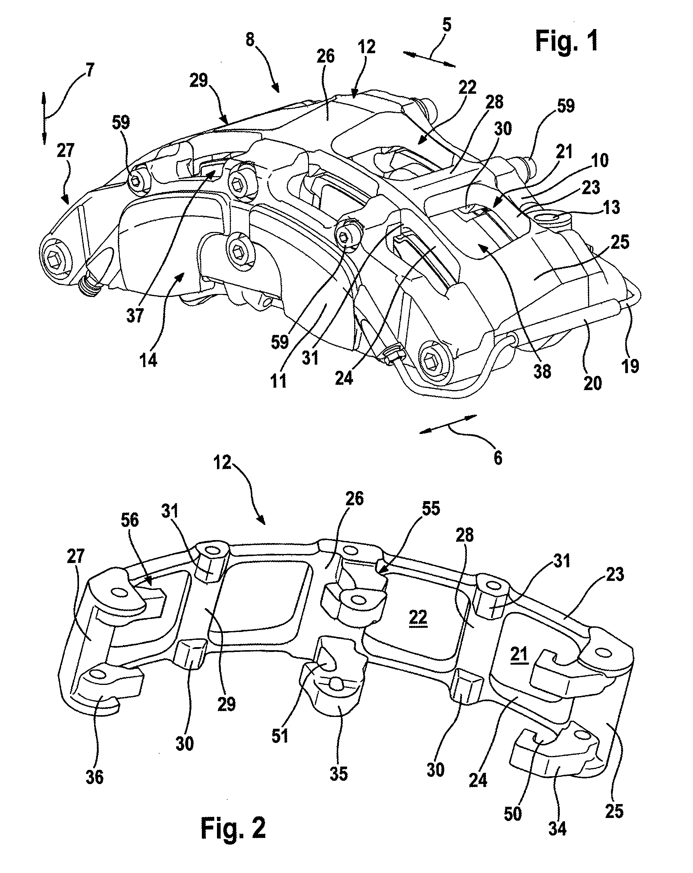
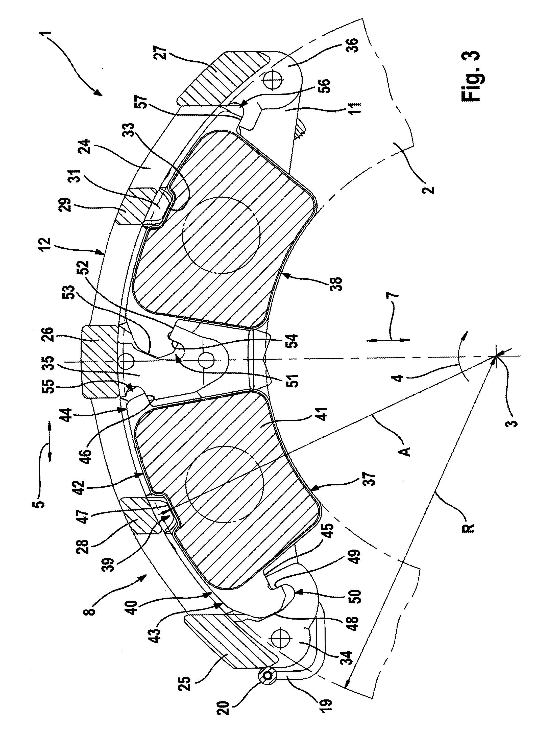
[0033]FIG. 1 to FIG. 6 show a first embodiment of a disk brake 1. This disk brake 1 comprises a brake caliper 8 which is embodied as a fixed caliper and which can be mounted permanently on a vehicle limb (not illustrated). In the mounted state, the brake caliper 8 engages axially around a brake disk 2 which is mounted so as to be capable of rotating about a rotational axis 3. In this context, the brake disk 2 runs through a shaft 9 extending through the brake caliper 8 in the peripheral direction 5, said shaft 9 being formed by a first caliper limb 10 facing the vehicle, a caliper bridge 12 and a second caliper limb 11 facing away from the vehicle. In the present case, the caliper limbs 10, 11 and the caliper bridge 12 are embodied as different components and are connected to one another by means of screws. It is also conceivable to embody the brake caliper in one piece. Substantially radially extending bores 13, by means of which the brake caliper 8 can be connected to the vehicle ...


PUM


Abstract

A disk brake having a brake caliper, which engages axially in a U shape around a rotatable brake disk is provided. The disk brake includes a caliper bridge, two caliper limbs and at least one actuating device. At least one brake lining is mounted in an axially movable fashion in the brake caliper. The caliper bridge has, in the peripheral direction, at least three substantially axially extending supports, wherein two of the supports are embodied as a main support and one support is embodied as a central support. These supports connect the two caliper limbs and in the process form two windows and axially project beyond the brake disk. The central support projects both beyond the brake disk and beyond the brake lining in the axial direction.

Description

CROSS REFERENCE TO RELATED APPLICATIONS[0001]This application is the U.S. national phase application of PCT International Application No. PCT / EP2007 / 053451, filed Apr. 10, 2007, which claims priority to German Patent Application No. DE102006018265.0, filed Apr. 20, 2006 and German Patent Application No. DE102007006472.3, filed Feb. 9, 2007, the contents of such applications being incorporated by reference herein in their entirety.BACKGROUND OF THE INVENTION[0002]1. Field of the Invention[0003]The invention relates to a disk brake having a brake caliper.[0004]2. Description of the Related Art[0005]DE 195 30 407 A1 discloses a disk brake which has a fixed caliper with caliper limbs and a caliper bridge. The caliper bridge is constructed here in the form of screws which function as a support and which connect the caliper limbs. Such brakes require a relatively large installation space in the radial and peripheral directions. In a disk brake it has a positive effect on the braking power...

Claims


Application Information

Patent Timeline
Patent Type & Authority Applications(United States)
IPC IPC(8): F16D55/228F16D65/092
CPCF16D55/226F16D2055/002F16D65/095F16D55/228F16D65/092F16D2055/0016F16D2055/0091F16D65/04
Inventor BACH, UWESUNDHEIM, RALFVAN AKEN, VOLKER
Owner CONTINENTAL TEVES AG & CO OHG
Why Eureka
Try Eureka