
Circuit for controlling an acceleration, braking and steering system of a vehicle

a technology for steering system and acceleration, applied in the direction of steering components, power-driven steering, vehicles, etc., can solve the problems of redundancy not only in the motor, but also in the control, and achieve the effect of simple circuitry

Active Publication Date: 2014-08-14
SCHAEFFLER PARAVAN TECH GMBH & CO KG
View PDF25 Cites 16 Cited by
  • Summary
  • Abstract
  • Description
  • Claims
  • Application Information

AI Technical Summary

Benefits of technology

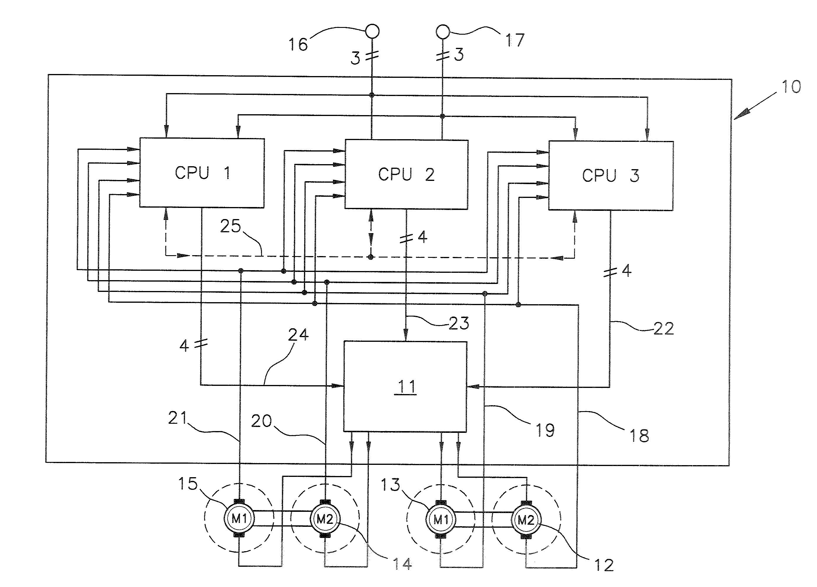
The patent text describes a system that uses programmable logic devices (CPLDs) to control motors in vehicles. This system eliminates the need for redundant components and can be easily installed in existing vehicles. The CPLDs provide a flexible logic matrix that can link input signals according to programmable rules, making it easy to control the direction and acceleration of the motors. This results in a more favorable and robust system compared to other options. The H-bridge circuits in the motors are controlled by signals from one of the CPUs. Overall, this system provides a cost-effective and efficient solution for controlling motors in vehicles.

Problems solved by technology

Redundancy is present not only in the motors, but also in the control of the braking and acceleration system and the steering system of the vehicle.

Method used


Image

  • Circuit for controlling an acceleration, braking and steering system of a vehicle
  • Circuit for controlling an acceleration, braking and steering system of a vehicle

Examples


Embodiment Construction

[0019]The following is a detailed description of at least one example embodiment of the invention depicted in the accompanying drawing. The example embodiments are presented in such detail as to clearly communicate the invention and are designed to make such embodiments obvious to a person of ordinary skill in the art. However, the amount of detail offered is not intended to limit the anticipated variations of embodiments; on the contrary, the intention is to cover all modifications, equivalents, and alternatives falling within the spirit and scope of the present invention, as defined by the appended claims.

[0020]The invention is described in greater detail in the following by reference to a the circuit of FIG. 1, which shows a control unit 10 and motors 12, 13 for the braking and acceleration system, and motors 14, 15 for the steering of a non-illustrated vehicle.

[0021]The control unit 10 comprises three CPUs, namely CPU1, CPU2, CPU3. The three CPUs, namely CPU1, CPU2, CPU3, are id...


PUM


Abstract

A circuit for controlling an acceleration, braking and steering system of a vehicle having at least two separate motors for actuating the acceleration and braking system, at least two separate motors for actuating the steering system and at least one electronic control unit for controlling the motors. The control unit comprises three identical CPUs and one programmable logic component. Each of the CPUs generates control signals for the motors depending on input control signals and sensor signals of the motors and forwards these control signals to the programmable logic component. The programmable logic component, depending on its programming, forwards the control signals of one of the CPUs to the motors.

Description

CROSS-REFERENCE TO A RELATED APPLICATION[0001]The invention described and claimed hereinbelow is also described in German Priority Document DE 10 2013 202253.0, filed on Feb. 12, 2013. The German Priority Document, the subject matter of which is incorporated herein by reference, provides the basis for a claim of priority of invention under 35 U.S.C. 119(a)-(d).BACKGROUND OF THE INVENTION[0002]The invention relates to a circuit for controlling an acceleration, braking, and steering system of a vehicle having at least two separate motors for actuating the acceleration and braking system, at least two separate motors for actuating the steering system and at least one electronic control unit for controlling the at least two separate motors for actuating the acceleration and braking system and the at least two separate motors for actuating the steering system.[0003]A circuit that relates to the invention is described in DE 10 2006 062 300 B4 and comprises two control units, namely one fo...

Claims


Application Information

Patent Timeline
Patent Type & Authority Applications(United States)
IPC IPC(8): B60R16/023
CPCB60R16/0231B60W2050/0006B60W2050/0292B60W50/023B62D5/04B62D5/0493B60L3/0092G06F11/1629G06F11/1633G06F11/1641G06F11/184Y02T10/64
Inventor ARNOLD, ROLANDKOTROTSIOS, GEORG
Owner SCHAEFFLER PARAVAN TECH GMBH & CO KG
Learn More