
Multi-band antenna

a multi-band antenna and antenna technology, applied in the direction of resonant antennas, antenna earthings, radiating elements structural forms, etc., can solve the problems of increasing interference between antennas and insufficient bandwidth of antennas b>1/b>′, and achieve the effect of low cost and easy manufacturing

Inactive Publication Date: 2008-11-04
HON HAI PRECISION IND CO LTD
View PDF7 Cites 36 Cited by
  • Summary
  • Abstract
  • Description
  • Claims
  • Application Information

AI Technical Summary

Benefits of technology

The present invention provides a multi-band antenna that integrates the antennas for WWAN and WLAN, with the benefits of mini-structure, easy manufacturing, and low cost. The antenna has a reduced installation space and excellent performance. The first antenna has a metallic sheet, insulative member, and metal foil, while the second antenna has a grounding portion. These features make the antenna ideal for use in various wireless communication devices.

Problems solved by technology

It arises a hot problem to integrate two individual antennas in a limited space to go along with the miniaturization of portal devices.
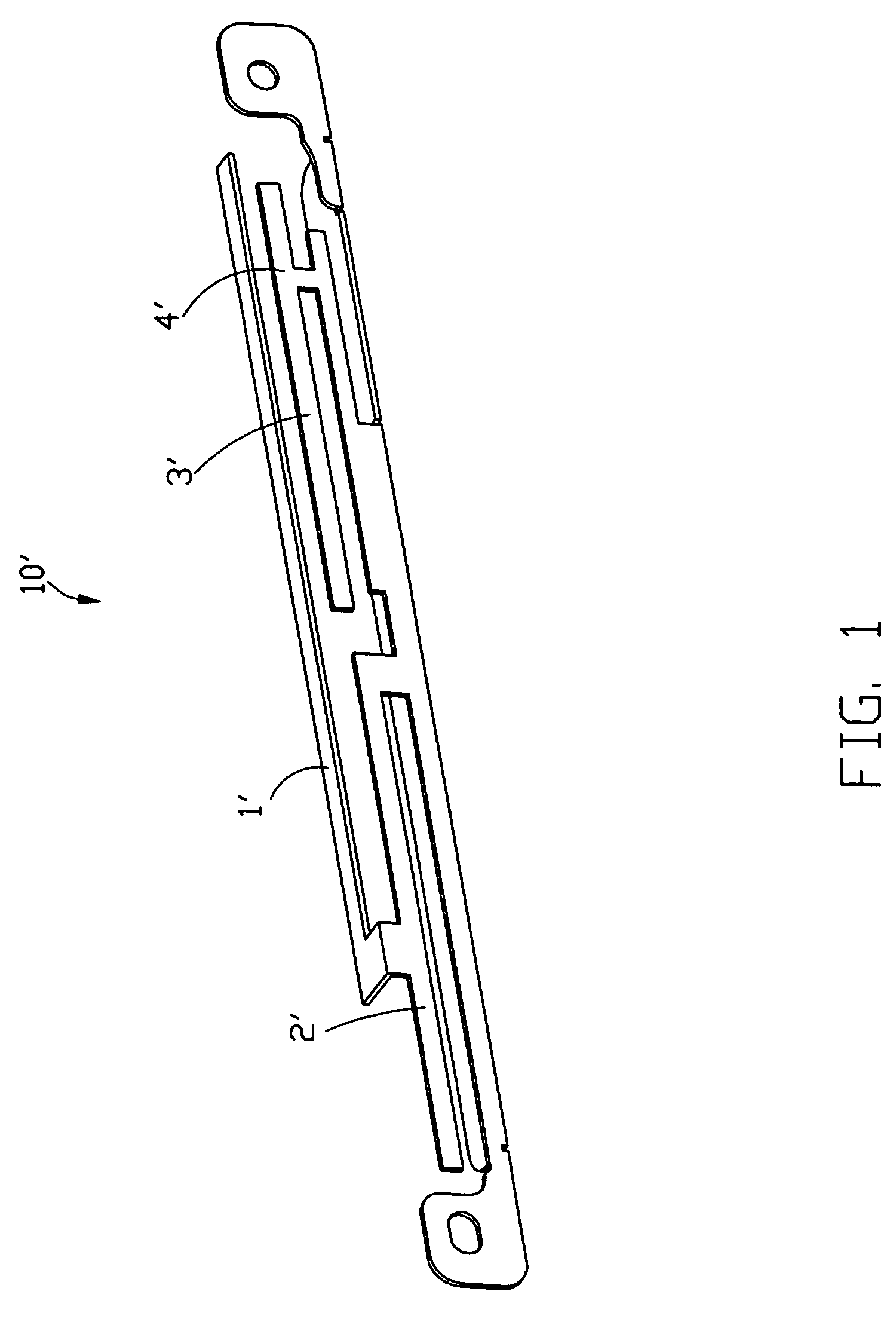
However, with the two types of antennas integration, the interference therebetween will become greater, and owing to this structure, the antenna 1′ can not achieve enough bandwidth.

Method used


Image

  • Multi-band antenna
  • Multi-band antenna
  • Multi-band antenna

Examples


Embodiment Construction

[0016]Reference will now be made in detail to the preferred embodiment of the present invention.

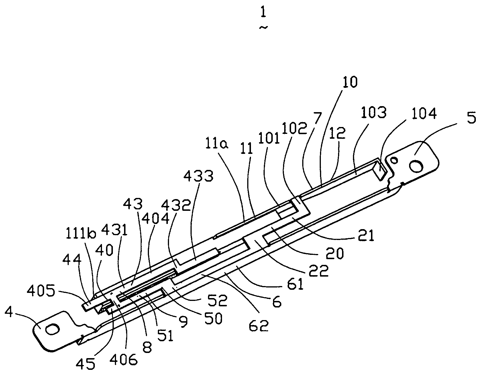
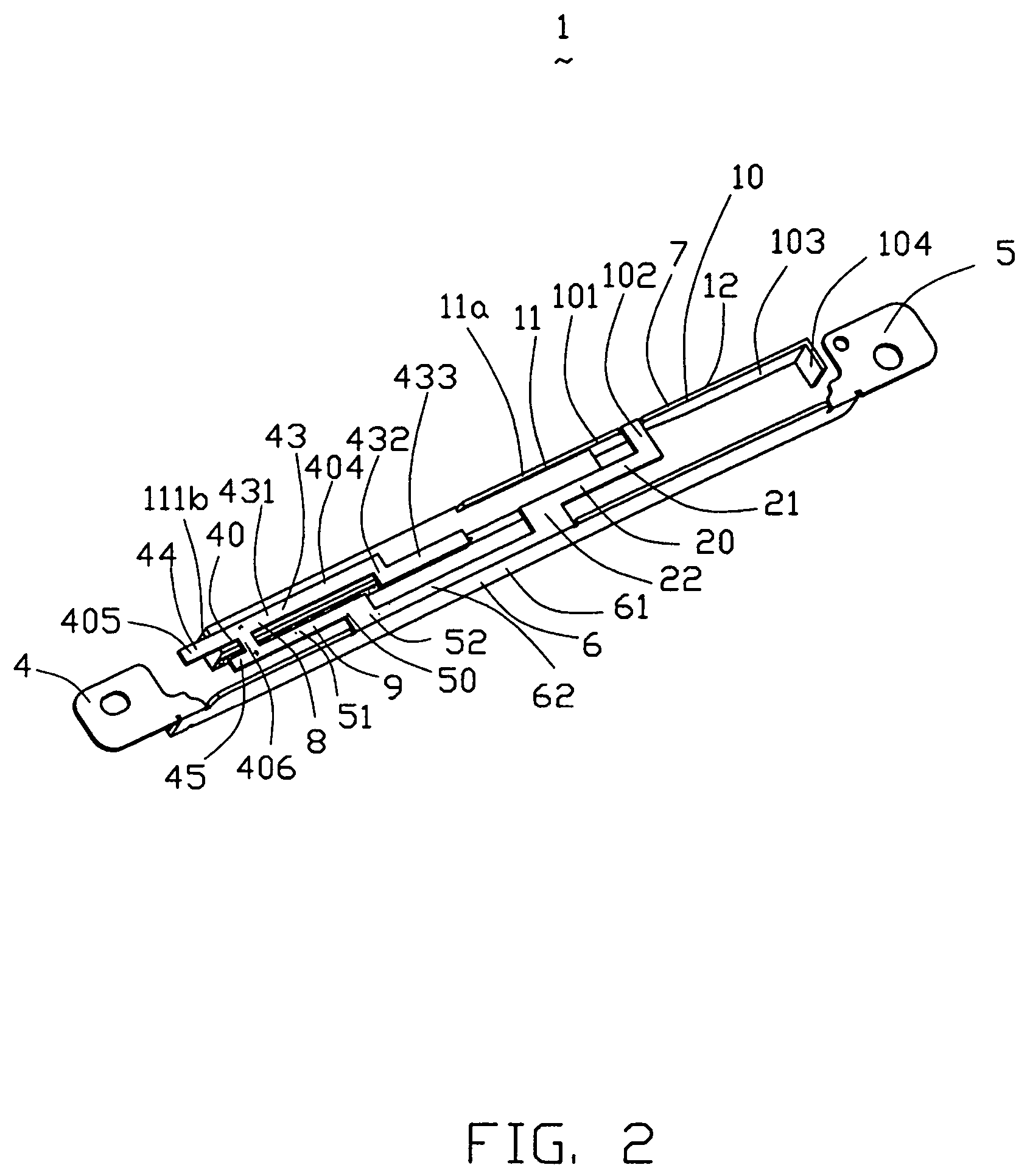
[0017]Referring to FIGS. 2-6, a multi-band antenna 1 in accordance with a preferred embodiment of the present invention consists of an antenna body 100, an insulative member 112 affixed to the antenna body 100 and a metal foil 113. The multi-band antenna 1 comprises a first antenna 2 used in WWAN, a second antenna 3 used in WLAN and a grounding portion 6 employed in each antenna 2, 3. The grounding portion 6 comprises a first grounding portion 61 and a bending portion 62 perpendicularly extending from the first grounding portion 61. The multi-band antenna 1 is integrally made from a metal sheet and integrates the first type of antenna for WWAN and the second type of antenna for WLAN together.

[0018]The first antenna 2 comprises a first radiating member 10, a first connecting portion 20 and the grounding portion 6. The first radiating member 10 comprises a first radiating portion 11 and a s...


PUM


Abstract

A multi-band antenna includes a first antenna operating at wireless wide area network and having a first radiating arm, a second antenna operating at wireless local area network and a grounding portion employed by the first antenna and the second antenna. Wherein the first radiating arm of the first antenna further includes a metallic sheet, an insulative member affixed to the metallic sheet and a metal foil affixed to the insulative member.

Description

BACKGROUND OF THE INVENTION[0001]1. Field of the Invention[0002]The present invention relates generally to an antenna, and more particularly to a multi-band antenna used for electronic devices, such as notebook.[0003]2. Description of Prior Art[0004]With the high-speed development of the mobile communication, people more and more expect to use a computer or other portable terminals to optionally connect to Internet. GPRS (General Packer Radio Service) and WLAN (Wireless Local Area Network) allow users to access data wirelessly over both cellular networks and 802.11b WLAN system. When operating in GPRS, the data transmitting speed is up to 30 Kbps˜50 Kbps, while when connected to a WLAN access point, the data transmitting speed is up to 11 Mbps. People can select different PC cards and cooperate with the portable terminals such as the notebook computer or the like. to optionally connect to Internet. Since WLAN has a higher transmitting speed, WLAN is usually used to provide public WL...

Claims


Application Information

Patent Timeline
Patent Type & Authority Patents(United States)
IPC IPC(8): H01Q1/24
CPCH01Q1/243H01Q5/40H01Q5/371H01Q1/38
Inventor HUNG, CHEN-TAKU, PO-KANGHUANG, YAO-SHIEN
Owner HON HAI PRECISION IND CO LTD
Learn More