Apparatus for peripheral vascular access

a peripheral vascular and appendix technology, applied in the direction of dilators, catheters, other medical devices, etc., can solve the problems of hematoma formation in surrounding tissue, associated pain and discomfort of patients, and still required significant skill for correct needle insertion

Active Publication Date: 2012-01-31
I V ACCESS TECH
View PDF9 Cites 40 Cited by
  • Summary
  • Abstract
  • Description
  • Claims
  • Application Information

AI Technical Summary

Benefits of technology

[0012]It is an object of this invention to provide an intra-vascular catheter apparatus that utilizes a relatively small bore guide needle and guide dilator to make insertion of an intra-vascular catheter easier to achieve and less painful for patients than conventional intra-vascular guide needles and catheters. It is another object of this invention to provide an intra-vascular catheter apparatus that employs a means of shielding the guide needle tip after insertion into the target vessel to prevent the needle tip from damaging or penetrating the opposite wall of the vessel during final catheter placement. It is another object of this invention to provide an intra-vascular catheter apparatus with a one way valve that prevents blood leakage after the catheter has been inserted into the patient's vessel, the guide needle is fully retracted, and as the intra-vascular fluid connection is attached to the catheter hub. These and other objects of this invention are achieved by an intra-vascular catheter apparatus comprising a guide needle having a distal end with a tapered and / or beveled puncturing / piercing tip and a proximal end onto which is attached a hub, and a smooth section connecting the distal and proximal ends, and a guide dilator with an inside diameter approximately the same as the outside diameter of the guide needle, a tapered distal end and a proximal end connected to a hub shaped such that a portion of the guide needle hub fits concentrically and slides axially within the dilator hub. The length of the guide dilator can be such that the guide needle, when fully inserted into the catheter, protrudes only enough to expose the beveled and / or tapered piercing tip of the needle. The apparatus further can include an intra-vascular catheter, the length of which is such that the guide dilator, when fully inserted into the intra-vascular catheter, protrudes only enough to expose the tapered tip of the guide dilator. The intra-vascular catheter can have an inside diameter the same as the outside diameter of the guide dilator, a tapered distal end, and a proximal end connected to a hub that provides a fluid-tight seal between the inside of the catheter and the exterior of the dilator hub.
[0014]Placement of the intra-vascular catheter into a patient's blood vessel can be accomplished by first inserting the tip of the guide needle through the skin and penetrating the vessel wall, followed by the tapered distal tip of the guide dilator. The guide needle can then be retracted back into the guide dilator, e.g., until the hub of the guide needle contacts a mechanical stop in the guide dilator hub. At that point, the guide needle tip is preferably covered by the guide dilator. A spring loaded stop tab in the guide needle hub can prevent the needle from becoming exposed again and possibly piercing the other wall of the vessel. The guide dilator can be inserted further into the vessel, e.g., along with the tapered distal tip of an intra-vascular catheter to penetrate the wall of the vessel to a desired position of full insertion. The guide dilator, with the guide needle safely enclosed within, can be fully withdrawn from the intra-vascular catheter hub. A resilient valve, with an orifice forming a liquid-tight seal against the exterior surface of the guide dilator hub, can have sufficient elasticity to close when the needle and dilator are fully withdrawn, thereby preventing blood leakage from the catheter proximal opening.
[0029]A “resilient” material tends to return to its original position when a deforming force is removed. A resilient seal typically comprises a seal formed when a device component is forced to slide through and deform a resilient seal component, so that the resilient component is urged against the surface of the device component leaving no space therebetween. Typical resilient seals include resilient septa, sleeves and / or O-rings. A resilient dilator or catheter is characterized by an ability to resiliently flex and bend along the central axis, e.g., to reduce physical stresses at an insertion site and / or to conform with the path of a vessel into which they are inserted.
[0033]A catch is a mechanical feature on a device that stops and prevents a movement of one device relative to another. The catch can take any of a variety of forms and shapes, but is designed so that if the position of one device changes relative to another and a catch is contacted, further movement of the one device relative to the other is prevented.
[0041]A tapered tip in the context of the invention is a tip of a catheter, dilator or guide needle whereby the outside diameter of the tube decreases approaching the distal end, thus making the tube wall thinner. During piercing or insertion through skin or a vessel wall, a tapered tip can facilitate expansion of a pierced hole from one diameter to a larger diameter.
[0043]A flash cup is a mechanical feature that may be incorporated into the guide needle hub, allowing the caregiver to detect when the vessel wall has been punctured by virtue of vessel fluid filling the flash cup chamber.

Problems solved by technology

Should significant movement of the rigid needle take place, the vessel could be punctured from the inside causing a hematoma to form in the surrounding tissue with associated pain and discomfort to the patient.
While this technique was much simpler than surgical placement of the needle, it still required significant skill for correct needle insertion, and substantial restriction of patient movement to prevent complications from the stainless steel needle damaging the vessel or becoming displaced from the vessel.
However, for catheterizations that involve relatively high rates of fluid transfer, relatively large bore catheters are required.
Partial puncture into the side of the vessel or a complete miss of the targeted vessel can require a one or more additional attempts, causing pain and suffering for the patient, and substantial anxiety for the caregiver.
While the materials cited have provided improved comfort in intra-vascular catheters, the guide needle has continued to be a major source of pain and complications for catheterization procedures.
So the problems of initial pain at the time of skin and vessel puncture, as well as the difficulty of finding and successfully penetrating the targeted vessel remain as key sources of anxiety for the patient and the caregiver.
Although this design may be suited for procedures requiring insertion of a guide wire, the geometry of the dilator and its insertion technique make it difficult to position a fluid intra-vascular catheter in the vessel without blood leakage since the means of advancing the needle, advancing the dilator, retracting the needle, further advancing the dilator, advancing the catheter, and then finally retracting the dilator is time consuming, can introduce pathogens or allow blood to escape, and requires extensive technician training.
With many of the described catheterization technologies, blood contamination is risked when an intra-vascular catheter is inserted.
However, the necessity of a plunger and introduction of needle or tubing through the plunger decreases the inside diameter of the catheter and reduces the fluid flow rates for this design.
This valve is bulky and decreases the size of the intra-vascular catheter.
It also cannot be opened by conventional devices used by those skilled in the art.

Method used


Image

  • Apparatus for peripheral vascular access
  • Apparatus for peripheral vascular access
  • Apparatus for peripheral vascular access

Examples


example 1

A Catheter Insertion Assembly

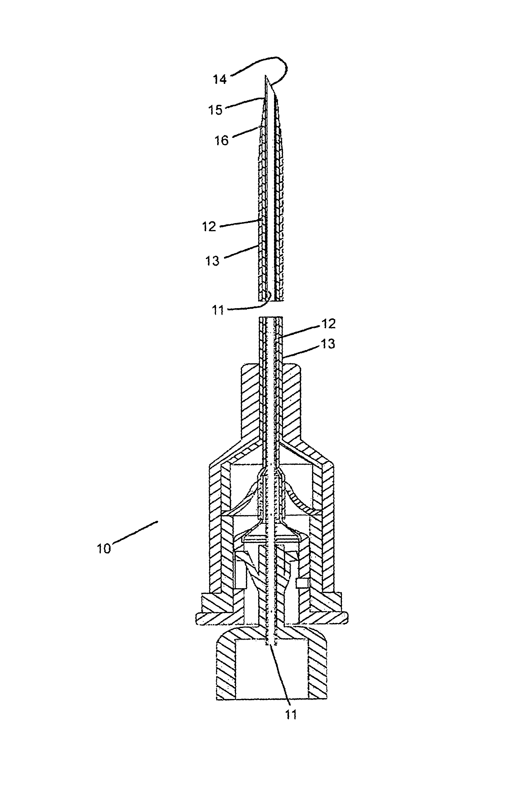
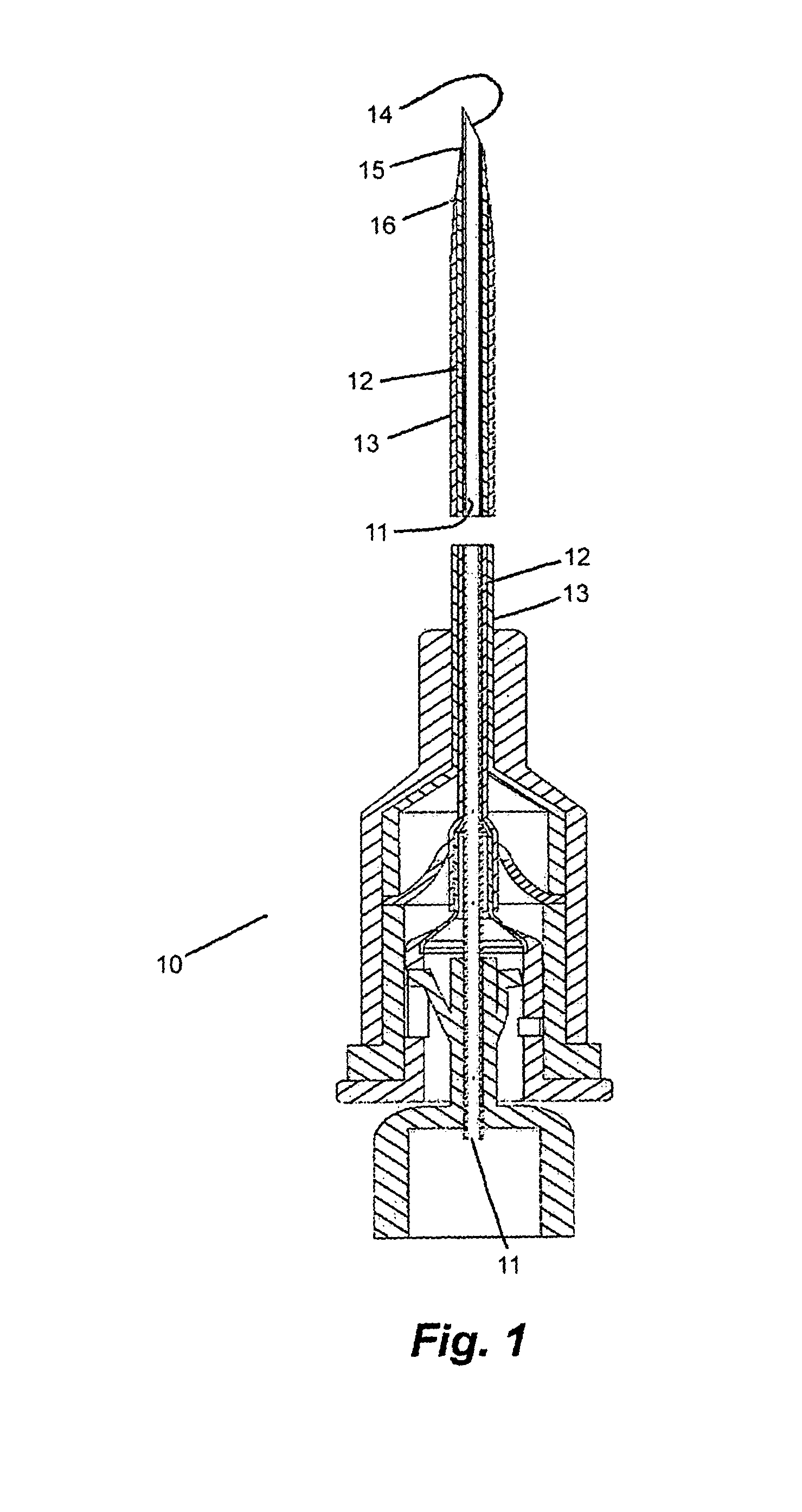
[0101]An exemplary catheter insertion assembly can be manufactured including a guide needle for perforation of skin and vessel; a guide dilator to expand the needle perforation, protect the vessel from further perforations and to guide a catheter into the vessel; and, a catheter to provide access to the vessel by clinical technicians.

[0102]FIG. 1 shows a catheter insertion assembly 10 composed of a guide needle 11, typically formed from stainless steel; a guide dilator 12, typically a tough, flexible plastic such as polyurethane or polytetrafluoroethylene; and, an intra-vascular catheter 13, also produced from a tough, flexible material, and of a geometry needed for a given medical procedure. These three components of the invention are fitted together concentrically such that the distal end 14 of the guide needle protrudes from the distal end 15 of the guide dilator, and the guide dilator protrudes from the distal end 16 of the intra-vascular catheter.

[0...

example 2

Needle Retraction Limiter

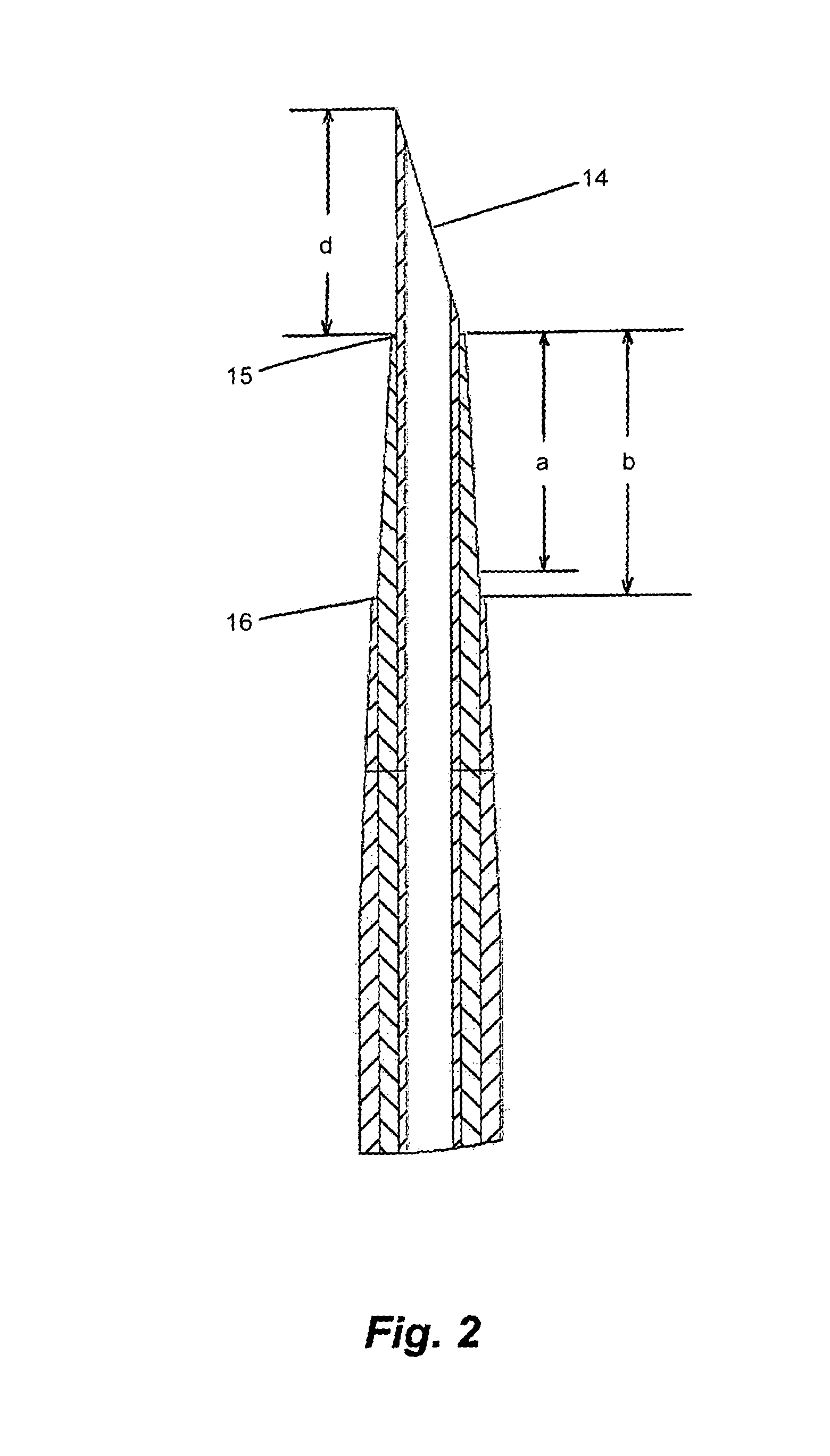
[0106]In FIG. 5, the guide needle hub, the guide dilator hub, the one way valve, and the catheter hub are shown in their typical relative positions at the time the distal end of the guide needle and catheter are manipulated to penetrate the skin and vessel wall as described in FIG. 4. The guide needle hub 23 contains two molded tangs, one 61 of which fits into a slot 62 in wall of the guide dilator hub. The slot limits the travel of the tang, and therefore limits the travel of the guide needle relative to the guide dilator. The open length of the slot, “c”, is greater than the distance that the distal end of the guide needle protrudes from the distal end of the catheter guide; length “d” in FIG. 2. The second tang 63, attached to the guide needle hub, is squeezed against the inner wall of the guide dilator hub, such that the arm 64 of the tang is under tension in a bent mode. The elastic nature of the plastic used to produce the guide needle hub causes the t...

example 3

Withdrawal of Guides from the Assembly

[0109]Once the intra-vascular catheter is in position, the catheter body is held and further outward axial pressure on the guide needle allows the guide needle and guide dilator to be withdrawn from the catheter body / intra-vascular catheter / catheter body plug assembly. FIG. 8 shows the intra-vascular catheter 13 has been positioned fully in the targeted vessel 52 and the guide dilator and guide needle completely withdrawn.

[0110]FIG. 9 shows the corresponding view of the catheter body, the intra-vascular catheter, the catheter body plug, and the one way valve with its opening completely closed.

[0111]FIG. 10 shows an oblique view of the one way valve 17. The valve is composed of an outer flange 101, where it is held in position by the proximal end of the intra-vascular catheter and the catheter body plug; a generally conical shaped body 102 to make mechanical penetration easy in one direction and more difficult in the other; a rounded apex 103 in ...


PUM


Abstract

This invention provides devices and methods for insertion of a catheter into a vessel. The devices include coaxial slidably mounted needle, dilator and catheter components. The methods include piercing a vessel with the needle component, dilating the pierced hole with the dilator component, retraction of the needle component, insertion of the catheter and withdrawal of the dilator.

Description

CROSS-REFERENCE TO RELATED APPLICATIONS[0001]This application claims priority to and benefit of a prior U.S. Provisional Application No. 61 / 011,211, An Apparatus for Peripheral Vascular Access, by Stephen Richard Keyser, et al., filed Jan. 14, 2008. The full disclosure of the prior application is incorporated herein by reference.FIELD OF THE INVENTION[0002]The invention is directed to methods and devices to facilitate insertion of a catheter into a vessel. Devices include axially concentric assemblies of a piercing needle and a flexible dilator that can guide an outer catheter into a vessel, such as a blood vessel. The proximal hub ends of such assemblies can have water triggered needle retraction mechanisms and / or lock mechanisms to control needle positioning during catheterization processes.BACKGROUND OF THE INVENTION[0003]Early technology for vascular access required surgical opening of the skin, viewing of the vessel to be catheterized, and placement, under sterile procedure of ...

Claims


Application Information

Patent Timeline
Patent Type & Authority Patents(United States)
IPC IPC(8): A61M5/178
CPCA61M25/0606A61M25/0631A61M39/24A61M25/0625A61M25/0693A61M29/02A61M5/3234A61M2205/02
Inventor KEYSER, STEPHEN RICHARDMILLER, III, JAMES EDGERLYMILLER, LEGAL REPRESENTATIVE, LINDA
Owner I V ACCESS TECH
Why Eureka
Try Eureka