

Wireless power feeder and wireless power receiver
a technology of wireless power receiver and wireless ac, which is applied in the direction of charging stations, electric vehicle charging technology, transportation and packaging, etc., can solve the problems of unfavorable increase in vehicle weight, and achieve the effect of stably providing power to the receiving body
- Summary
- Abstract
- Description
- Claims
- Application Information
AI Technical Summary
Benefits of technology
Problems solved by technology
Method used
Image

Examples
first embodiment
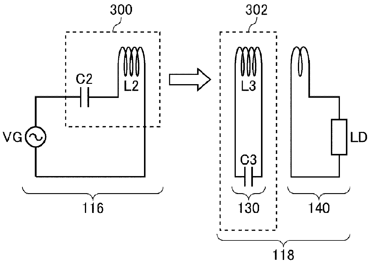
[0052]FIG. 1 is a view illustrating operation principle of a wireless power transmission system 100 according to the first embodiment. The wireless power transmission system 100 in the first embodiment includes a wireless power feeder 116 and a wireless power receiver 118. The wireless power feeder 116 includes a power feeding LC resonance circuit 300. The wireless power receiver 118 includes a receiving coil circuit 130 and a loading circuit 140. A power receiving LC resonance circuit 302 is formed by the receiving coil circuit 130.
[0053]The power feeding LC resonance circuit 300 includes a capacitor C2 and a feeding coil L2. The power receiving LC resonance circuit 302 includes a capacitor C3 and a receiving coil L3. The values of the capacitor C2, feeding coil L2, capacitor C3, and receiving coil L3 are set such that the resonance frequencies of the feeding LC resonance circuit 300 and receiving LC resonance circuit 302 coincide with each other in a state where the feeding coil L...
second embodiment
[0113]FIG. 14 is a view illustrating operation principle of the wireless power transmission system 100 according to a second embodiment. As in the case of the first embodiment, the wireless power transmission system 100 according to the second embodiment includes the wireless power feeder 116 and wireless power receiver 118. However, although the wireless power receiver 118 includes the power receiving LC resonance circuit 302, the wireless power feeder 116 does not include the power feeding LC resonance circuit 300. That is, the feeding coil L2 does not constitute a part of the LC resonance circuit. More specifically, the feeding coil L2 does not form any resonance circuit with other circuit elements included in the wireless power feeder 116. No capacitor is connected in series or in parallel to the feeding coil L2. Thus, the feeding coil L2 does not resonate in a frequency at which power transmission is performed.
[0114]The power feeding source VG supplies AC current of the resonan...
third embodiment
[0117]FIG. 16 is a plan view of a table 138 in which a plurality of feeding coils L2 are buried. The feeding coil L2 may be arranged not only in a line but also in a two-dimensional manner on a plane as the surface of the table 138.
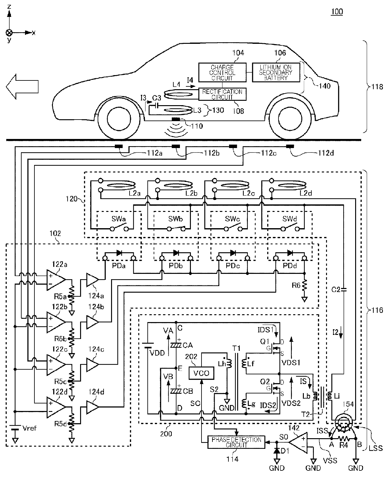
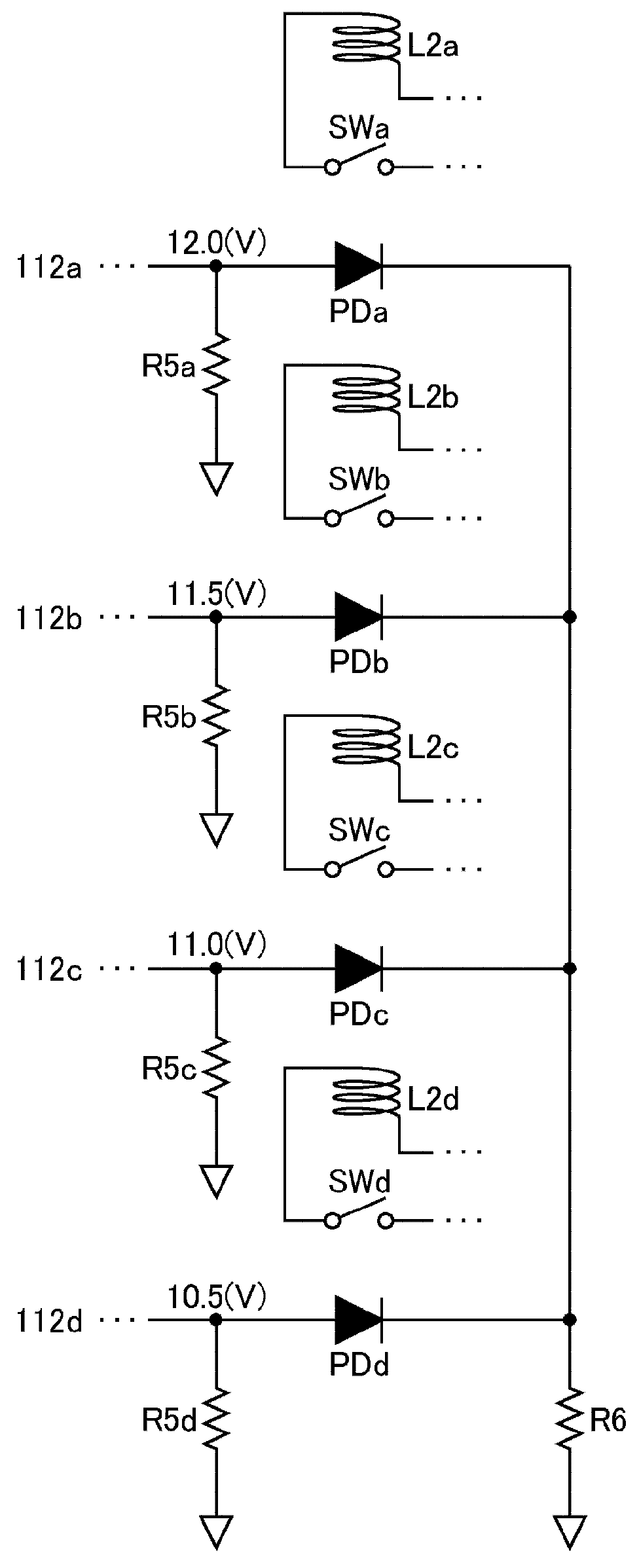
[0118]FIG. 17 is a cross-sectional view illustrating a state where a lamp 142 formed as the wireless power receiver 118 is disposed on the table 138. The wireless power feeder 116 of the first and second embodiments may be formed so as to control the plurality of feeding coils L2 two-dimensionally arranged on the table 138. The lamp 142 is formed as the wireless power receiver 118 including the receiving coil L3 and loading coil L4. One feeding coil L2 is selected depending on the position at which the lamp 142 is placed. As a result, power is fed by wireless from the most appropriate feeding coil L2 to the lamp 142 irrespective of the position of the lamp 142.
PUM
 Abstract
Description
Claims
Application Information