Hybrid drive device

A driving device and hybrid technology, which is applied in power devices, hybrid vehicles, pneumatic power devices, etc., can solve the problems of inability to lubricate and cool evenly over the entire circumference, and achieve miniaturization and axial The effect of miniaturization and simple structure

Inactive Publication Date: 2014-08-13
AISIN AW CO LTD
View PDF6 Cites 15 Cited by
  • Summary
  • Abstract
  • Description
  • Claims
  • Application Information

AI Technical Summary

Problems solved by technology

[0008] In the lubricating and cooling of the lubricating oil sprayed from the outer diameter side of the above-mentioned electric motor, the discharge ports are limited to a plurality of positions on the outer diameter side of the stator, and the lubricating oil is concentrated at a predetermined position of the stator, so that it is impossible to lubricate evenly over the entire circumference. cool down

Method used


Image

  • Hybrid drive device
  • Hybrid drive device
  • Hybrid drive device

Examples


Embodiment Construction

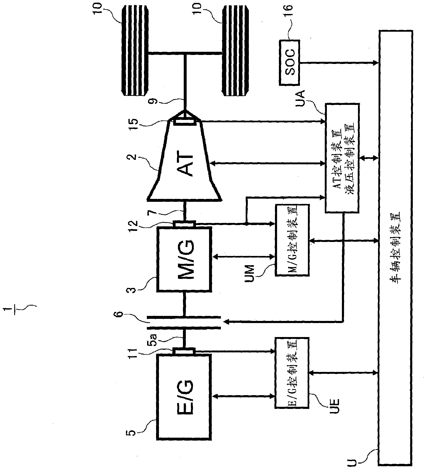
[0043]Embodiments of the present invention will be described below with reference to the drawings. Such as figure 1 As shown, the hybrid drive device 1 is constituted by a so-called single-motor type, and includes an automatic transmission device 2, a rotating electric machine (hereinafter referred to as an electric motor) 3, and a rotating part (rotor) disposed on the electric motor 3 and an internal combustion engine. 5 disconnects the clutch 6 (hereinafter referred to as K0 clutch) between the output shaft (coupling shaft) 5a of 5. An input member (hereinafter referred to as an input shaft) 7 of the automatic transmission 2 is connected to the rotating portion of the electric motor 3 , and an output member (hereinafter referred to as an output shaft) 9 thereof is connected to drive wheels 10 . The above-mentioned internal combustion engine 5, electric motor 3 and automatic transmission device 2 (including K0 clutch 6) are respectively controlled by engine (E / G) control de...


PUM


Abstract

This hybrid drive device separates the lubricant supplied to a clutch and to an electric motor and improves lubrication and cooling of the clutch and electric motor. Lubricant from a clutch lubrication hole (143) and an electric motor lubrication hole (145) and consisting of shaft core lubrication is partitioned by a rotor support member (126). The lubricant which lubricates the clutch (6) and flows out is separated by the cover member (187) and does not flow into the coil end (24a) on one side. The electric motor lubricant is guided to the coil end (24b) on the other side, and, passing through an oil passage (186), is guided to the coil end (24a) on the first side.

Description

technical field [0001] The present invention relates to a hybrid drive device having an internal combustion engine and an electric motor (rotary electric machine) as drive sources, and specifically relates to a single-motor type hybrid drive that disconnects the engine and transmits power from the internal combustion engine to an automatic transmission via a (K0) clutch Circulation of lubricating (cooling) oil in the drive unit. Background technique [0002] Conventionally, a single-motor type hybrid drive device has been proposed in which an output shaft (part) of an internal combustion engine is connected to an input shaft (part) of an automatic transmission via a K0 clutch, and a rotor of an electric motor is connected to an automatic transmission. device connection. Generally, the hybrid drive starts using the driving force of the electric motor, engages the K0 clutch at a predetermined low speed to start the engine, and uses the driving force of the engine to shift the...

Claims


Application Information

Patent Timeline
Patent Type & Authority Applications(China)
IPC IPC(8): B60K6/38B60K6/26B60K6/48B60K6/54B60W10/02B60W20/00F16D25/12B60L50/16
CPCB60K6/26B60K6/38F16D25/123B60K6/54F02B63/042B60K6/40F16D25/0638B60W20/00Y02T10/6221F16H57/0476B60K6/387B60W10/02Y10T74/19014B60K6/48Y02T10/62
Inventor 糟谷悟鬼头昌士关祐一新谷浩树
Owner AISIN AW CO LTD
Why Eureka
Try Eureka