Power unit cooling device

一种动力单元、冷却装置的技术,应用在动力装置、动力装置的冷却结合的布置、发动机的冷却等方向,能够解决空气热交换能力降低、很难机器冷却等问题,达到减小体积、提高冷却效果、降低生产成本的效果

Inactive Publication Date: 2006-02-15
HONDA MOTOR CO LTD
View PDF1 Cites 16 Cited by
  • Summary
  • Abstract
  • Description
  • Claims
  • Application Information

AI Technical Summary

Problems solved by technology

[0005] Yet this existing cooling device, because its structure is to make the air that introduces circulates inside the housing through the radial blowing effect of the centrifugal fan, therefore, when the position of the heat-generating rotating machinery that produces high heat such as clutch and When the distance between the rotating shafts of the centrifugal fan is large, it is difficult to cool the machine effectively
That is, in the case where the distance between the heat-generating rotating machine targeted for cooling and the rotating shaft of the centrifugal fan is large, the introduced air is warmed by other heat-generating machines while flowing in the housing, so when it reaches the cooling target When the heat-generating rotating machinery, the heat exchange capacity of the air has been reduced
In addition, from the characteristics of the centrifugal fan itself, even if it is arranged coaxially with the heat-generating rotating machine, it cannot directly supply air. The target heat-generating rotating machinery is placed at a certain distance

Method used


Image

  • Power unit cooling device
  • Power unit cooling device
  • Power unit cooling device

Examples


Embodiment Construction

[0030] Hereinafter, an embodiment of the present invention will be described with reference to the drawings.

[0031] In the following description, the front side refers to the direction in which the vehicle is advancing, and the right and left sides refer to the right and left sides when facing the direction in which the vehicle is advancing.

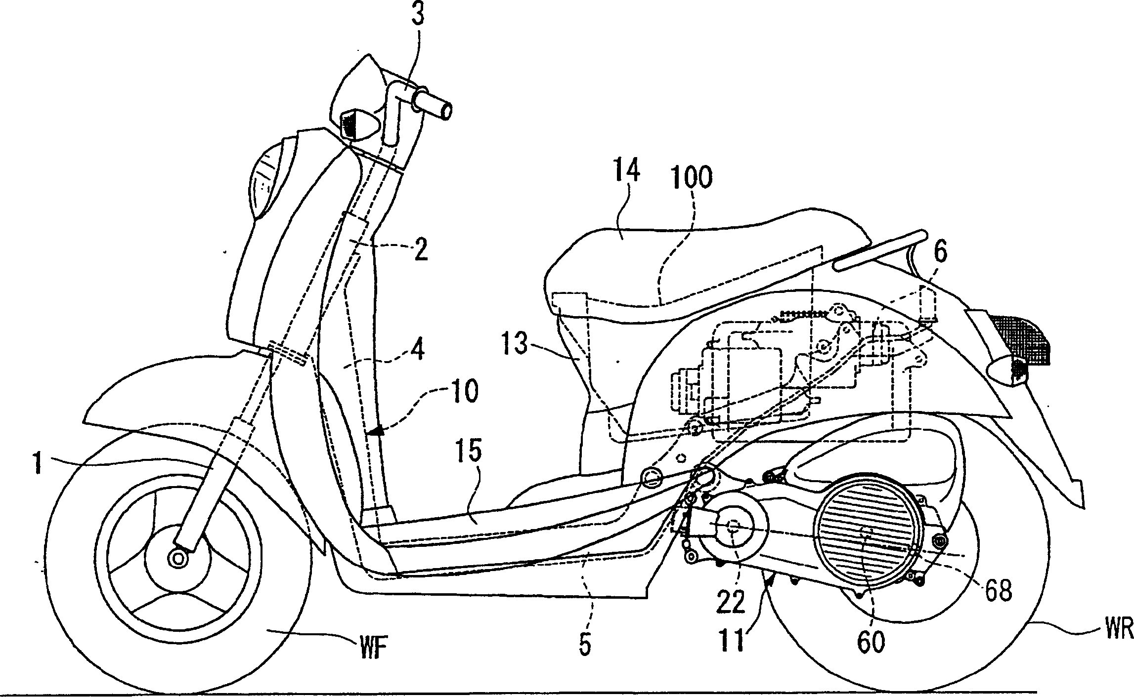
[0032] This embodiment is a case where the power unit cooling device of the present invention is used in a hybrid two-wheeled vehicle. Such as figure 1 As shown, the motorcycle of this embodiment is a so-called light motorcycle, and the power unit 11 including the power source is integrally swingable, and is supported on the vehicle body frame 10 so as to be swingable together with the rear wheel WR. At the front of the vehicle body is a front fork 1 pivotally supporting a front wheel WF, and the front fork 1 is rotatably supported by a head pipe 2 constituting a part of a vehicle body frame 10 . The upper end of the front fork 1 is ...


PUM


Abstract

To efficiently cool heat generation rotary equipment being a target in a casing.A centrifugal fan 54 is attached to an inner plate 40b of a centrifugal clutch 40 being the heat generation rotary equipment, and an intake port 59a of the casing is arranged in the vicinity of a front face in the axial direction of the centrifugal fan 54. The centrifugal fan 54 is provided with a base plate 86 connected with the inner plate 40b of the centrifugal clutch 40, a plurality of fins 87 provided on the base plate 86, a blow-out hole 88 passing through the base plate 86 in the axial direction between arbitrary ajacent fins 87, and a guide wall 89 for guiding air directed toward an outer side in the radial direction on the base plate 86 into the blow-out hole 88. The air immediately after being introduced from the intake port is blown to the centrifugal clutch in a rear part through the blow-out hole.

Description

technical field [0001] The present invention relates to an air-cooled cooling device for cooling the inside of a case of a power unit used in a vehicle such as a motorcycle with air flow. Background technique [0002] In an automatic two-wheeled vehicle, a power source such as an engine, and a power transmission mechanism such as a clutch and a continuously variable transmission are housed in a case and mounted on a vehicle frame as a power unit. In such a power unit, since various machines such as clutches and transmissions that generate heat during operation are accommodated in the housing, it is necessary to efficiently cool the inside of the housing. Therefore, most power units of this type are equipped with a cooling device that introduces air from the outside of the housing and circulates the air inside the housing to perform heat exchange. [0003] As a conventional cooling device, for example, there is a device in which a centrifugal fan is installed on the drive si...

Claims


Application Information

Patent Timeline
Patent Type & Authority Applications(China)
IPC IPC(8): F01P5/04F02B63/06F16H57/04B60K11/06B62K11/00F16D43/14F16H57/02F16H57/035
CPCB62M7/12F16H57/0415B62K2202/00F16D43/18Y02T10/6221B60K6/48F16H57/0489F01P1/06F16D13/72Y02T10/62F16D2043/145F16D2300/0212B62J50/30F16H57/04
Inventor 井元丰塚田善昭大关孝
Owner HONDA MOTOR CO LTD
Why Eureka
Try Eureka