Control of inductive power transfer pickups

a technology of inductive power transfer and control feature, which is applied in the direction of inductance, rail devices, ac networks with different sources at the same frequency, etc., can solve the problems of imposing a risk, catastrophic breakdown, and development of fire within the pickup device, so as to reduce the saturation capacity, reduce the risk, and ensure the control feature reliable

Inactive Publication Date: 2002-11-19
AUCKLAND UNISERVICES LTD
View PDF10 Cites 246 Cited by
  • Summary
  • Abstract
  • Description
  • Claims
  • Application Information

AI Technical Summary

Benefits of technology

The proposed secondary current limiting means is passive and relies on the bulk properties of a material. Therefore the invention should have a very reliable fail-safe control feature. Temperature rises, mechanical shocks, fractures, and the like reduce the saturation capacity. Only cooling can increase it. The risk of exceeding any ratings of ancillary components is now brought under control--as in

Problems solved by technology

While the constant-current characteristic of this type of inductive power transfer system is generally an advantage, it does impose a risk should a pickup coil enter a state in which there is no control over the amount of current collected.
An uncontrolled current resonating in a resonant secondary circuit forming part of a loosely coupled inductive power transfer system may build up to reach high levels if the circuit Q is large, whereupon a number of adverse results may occur, such as component failure, for example by overheating or breakdown of semiconductors or of dielectrics within resonating capacitors and apart from loss of function this can lead to the development of fire within the pickup device.
If such systems rely solely on active control to restrict the circulating current, then in the absence of function by the active control it is likely that a catastrophic breakdown will occur.
Cores of this type, driven into saturation will evolve heat from hysteresis losses, and cooling is not provided for in the region of the constriction, so this approach would result in a quite temperature-sensitive output voltage.

Method used


Image

  • Control of inductive power transfer pickups
  • Control of inductive power transfer pickups
  • Control of inductive power transfer pickups

Examples


example 1

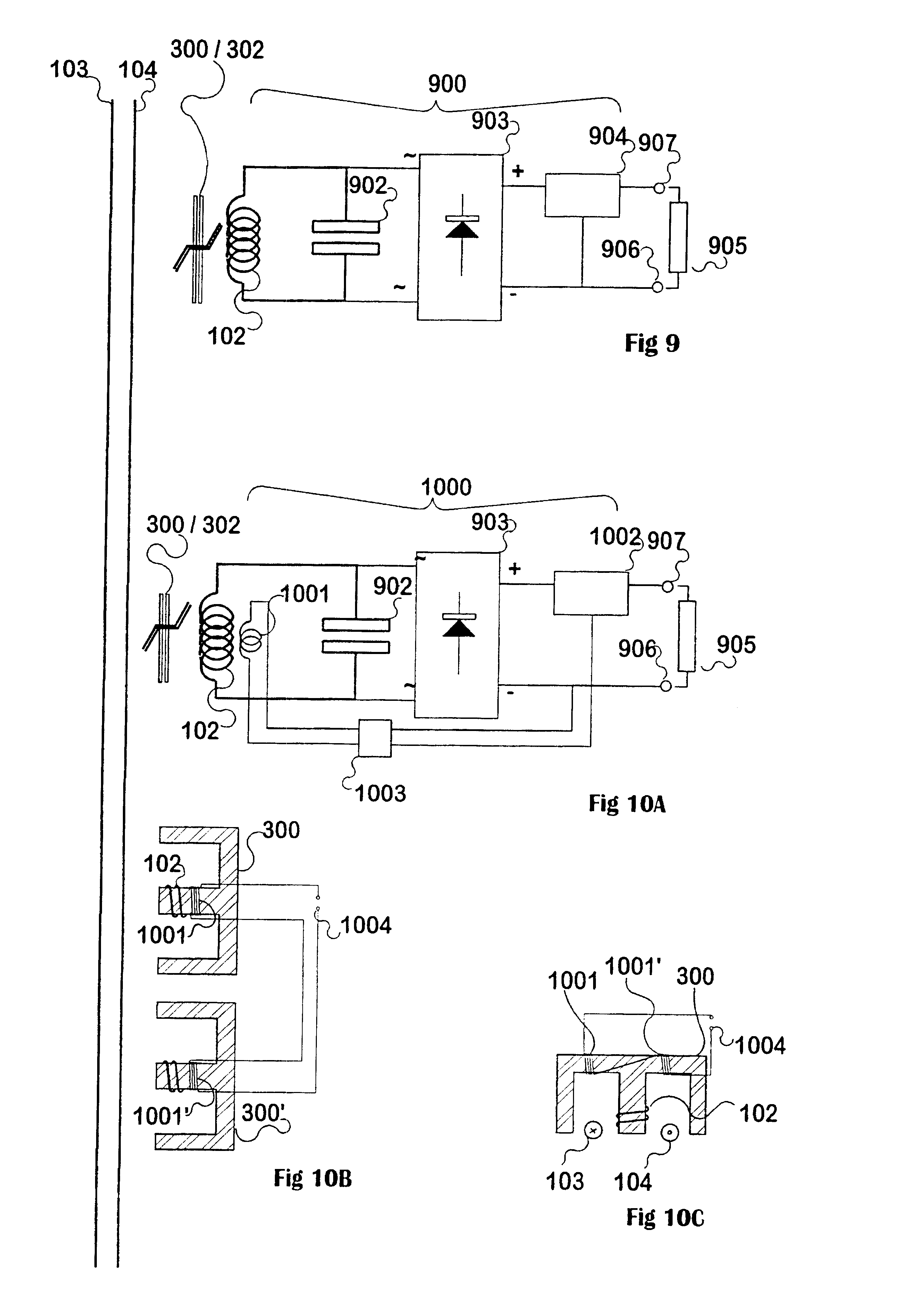
In a device using inductive power transfer for battery charging purposes the saturated-core pickup design has been designed so that the rectifier diodes are effectively protected from a voltage surge which will otherwise occur at any time that a shorting controller enters the "open" state, or at the initial connection of power. Because a constant-current supply exists, the immediate injection of full power results in a voltage surge because consumption rises more slowly. The rate of rise of current flow from the rectifier to the battery is limited by a series inductance.

The design process in respect of saturation comprises the provision of a core which will saturate, when at a low end of an operating temperature range, before the output voltage exceeds the peak inverse voltage rating of the rectifier diodes used. (The "low temperature" is specified only because the flux density at saturation reduces with increasing temperature). This application uses a bridge comprised of Schottky d...


PUM


Abstract

Secondary resonant pickup coils (102) used in loosely coupled inductive power transfer systems, with resonating capacitors (902) have high Q and could support large circulating currents which may destroy components. A current limit or "safety valve" uses an inductor designed to enter saturation at predetermined resonating currents somewhat above normal working levels. Saturation is immediate and passive. The constant-current characteristic of a loosely coupled, controlled pickup means that if the saturable section is shared by coupling flux and by leakage flux, then on saturation the current source is terminated in the saturated inductor, and little detuning from resonance occurs. Alternatively an external saturable inductor (1101, 1102) may be introduced within the resonant circuit (102 and 902), to detune the circuit away from the system frequency. Alternatively DC current may be passed through a winding to increase saturation of a saturable part of a core. As a result, a fail-safe pickup offering a voltage-limited constant-current output is provided.

Description

This invention relates to inductive power transfer; more particularly to loosely coupled systems for inductive power transfer, and in particular this invention relates to protection means for limiting the amount of current circulating in a secondary pickup coil of an inductive power transfer system.The general structure of an inductive power transfer installation is that there is a primary conductor (or more) energised with alternating current, and one or more secondary or pickup devices which intercept the changing flux surrounding the primary conductor and convert this flux into electrical energy by means of windings. Often the pickup devices are mobile, and move alongside, or sometimes (if internal energy storage is available) away from the primary conductors.There appears to be at least two distinct groups of inductive power transfer systems amongst the published literature. One group uses a "spread-out transformer" approach for the primary trackway, in which a series of iron la...

Claims


Application Information

Patent Timeline
Patent Type & Authority Patents(United States)
IPC IPC(8): B60L5/00H02J5/00H02J17/00B60M7/00
CPCB60L5/005H02J5/005B60L2200/26H02J50/12H02J3/06
Inventor BOYS, JOHN TALBOT
Owner AUCKLAND UNISERVICES LTD
Why Eureka
Try Eureka