Single-stage electronic ballast device

a single-stage electronic ballast and electronic ballast technology, applied in the direction of electric variable regulation, process and machine control, instruments, etc., can solve the problems of acoustic resonance of the above-mentioned electronic ballast, poor luminous efficiency of the hid lamp operated at high frequency, and difficult to solve, so as to reduce the complexity and use of active elements of the circuit, reduce the loss of conversion and electromagnetic interference of multi-stage circuits, and prevent malfunction caused by current switching

Active Publication Date: 2008-01-24
IND TECH RES INST
View PDF3 Cites 79 Cited by
  • Summary
  • Abstract
  • Description
  • Claims
  • Application Information

AI Technical Summary

Benefits of technology

[0015]It is the object of the present invention to provide a single-stage electronic ballast device for outputting a low frequency square wave current to drive at least one HID lamp. The circuit comple

Problems solved by technology

However, the above-mentioned electronic ballast suffers to the problem of acoustic resonance, especially to lamp 10 of lower rated power.
This problem is difficult to solve even through complicated detection or control is used.
Moreover, the HID lamp operated at high frequency has poor luminous efficiency.
1. The circuit is complicated with lots of active switching elements.
2. The overall conversion efficiency is reduced due to

Method used


Image

  • Single-stage electronic ballast device
  • Single-stage electronic ballast device
  • Single-stage electronic ballast device

Examples


Embodiment Construction

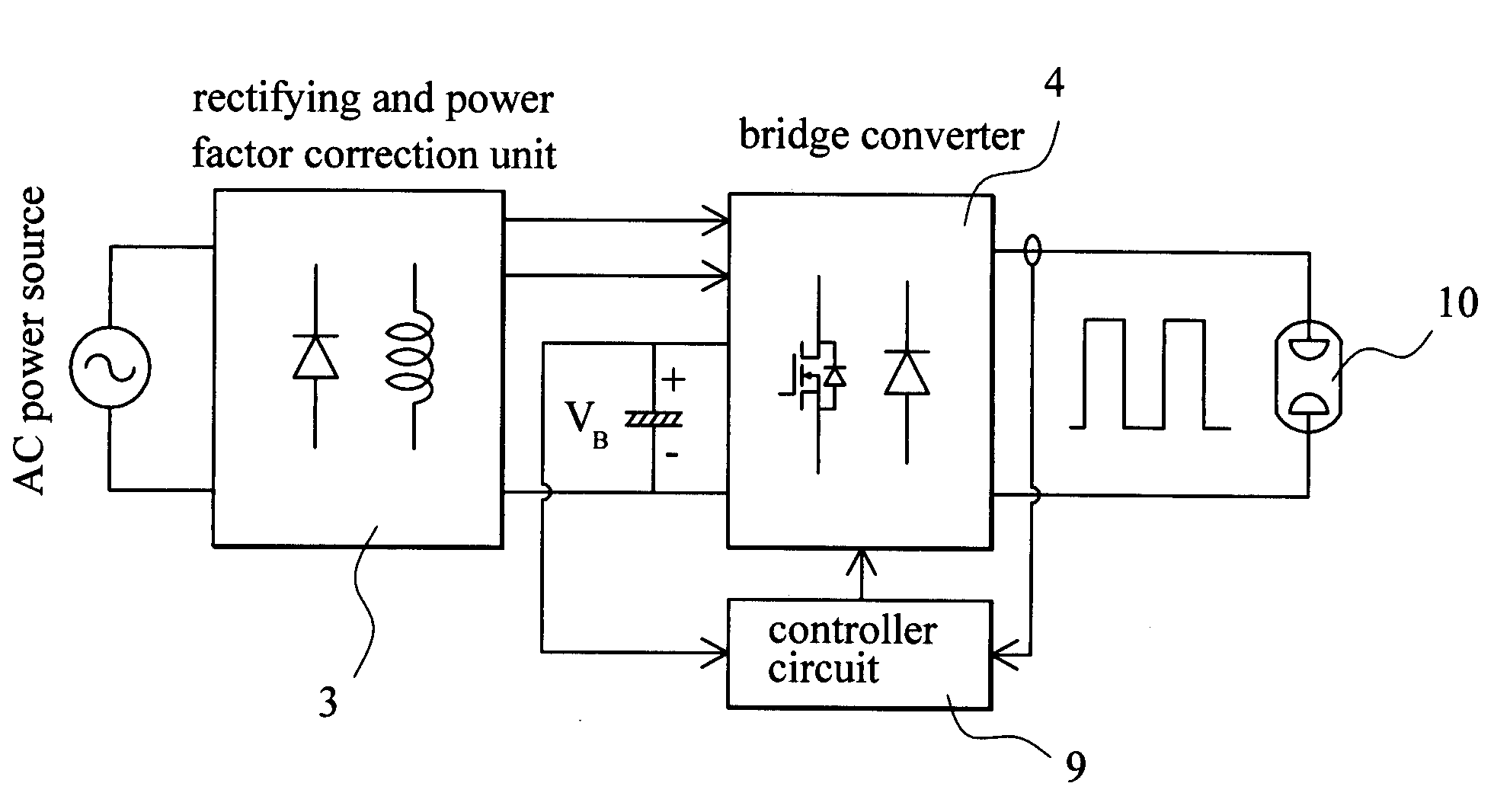
[0034]FIG. 3 is a block diagram of the single-stage electronic ballast. FIG. 4(a) to FIG. 4(e) shows the rectifying and power factor correction circuit according to five preferred embodiment of the present invention. The single-stage electronic ballast according to the present invention outputs low-frequency square wave and comprises mainly a bridge converter 4 and a rectifying and power factor correction unit 3.

[0035]The bridge converter 4 comprises four switching units Q1-Q4 to form arms of a full bridge. The connection node of the first switching unit Q1 and the fourth switching unit Q4 forms a first load terminal (node a). The connection node of the second switching unit Q2 and the third switching unit Q3 forms a second load terminal (node b). The connection node of the first switching unit Q1 and the second switching unit Q2 is connected to a positive node (+) of a DC link capacitor CB. The connection node of the third switching unit Q3 and the fourth switching unit Q4 is conne...


PUM


Abstract

A single-stage electronic ballast device outputs a square wave current to drive an HID lamp, which includes a rectifying and power factor correction unit, a bridge converter and a controller circuit. The rectifying and power factor correction unit has an input connected to an AC power source to rectify an AC power to a DC power. The bridge converter comprises two bridge arms formed by four switches, load terminals defined by midpoints of the two bridge arms and the HID lamp is connected between the load terminals. The bridge converter converts DC current to square wave current to drive the HID lamp with power control. The load terminals are selectively connected to output of the rectifying and power factor correction unit to adjust waveform of input current for higher power factor. The controller circuit has output connected to DC link voltage terminal and load terminal of the bridge converter.

Description

[0001]1. Field of the Invention[0002]The present invention relates to a single-stage electronic ballast device, especially to a high power factor single-stage electronic ballast device for outputting a low frequency square wave current to drive HID lamp.[0003]2. Description of Prior Art[0004]High intensity discharge (HID) lamps have the advantage of ultra brightness, power saving and low thermal energy, and are widely recognized as high quality lighting source. The nowadays electronic ballast for HID lamp can be operated with high-frequency sinusoidal wave current source or low-frequency square wave current source.[0005]FIG. 1 shows the circuit diagram of the electronic ballast of high-frequency sinusoidal wave current source, which has a simple circuit structure. The electronic ballast of high-frequency sinusoidal wave current source shown in this figure comprises a first-stage power factor correction unit 11 and a second-stage DC-AC converter 12. A resonance circuit 13 is used to ...

Claims


Application Information

Patent Timeline
IPC IPC(8): H05B41/36
CPCH05B41/2828Y02B20/202Y02B20/186H05B41/2888Y02B20/00
Inventor LEE, CHING-RANCHUNG, HWEI-SHUNG
Owner IND TECH RES INST
Why Eureka
Try Eureka