Electric power storage system using capacitors and control method thereof

a technology of capacitors and power storage systems, applied in the direction of electric variable regulation, process and machine control, instruments, etc., can solve the problems of significantly affecting charging/discharging characteristics, increasing voltage equalization loss, etc., and achieves high charging/discharging efficiency, reduced charging time, and improved charging efficiency

Inactive Publication Date: 2009-05-28
LIMITED COMPANY TM
View PDF8 Cites 53 Cited by
  • Summary
  • Abstract
  • Description
  • Claims
  • Application Information

AI Technical Summary

Benefits of technology

[0036]The present inventor has discovered that, due to these reasons, the charging / discharging pattern of EDLC inter-terminal voltage of each block fluctuates, thus increasing the voltage equalization loss and significantly affecting the charging / discharging characteristics. Specifically, in a charging process, if the capacitors of each block can be switched to a parallel connection in order of larger block voltage (when the EDLCs within a circuit block are connected in series, the total voltage Vb of each EDLC inter-terminal voltage is referred to as “block voltage”; when the EDLCs within a circuit block are connected in parallel, the average voltage Vb of each EDLC inter-terminal voltage is referred to as “block voltage”) and the EDLCs of a low-block voltage block having EDLCs once switched to a parallel connection can be returned to a serial connection, then charging can be performed more swiftly and voltage equalization loss can also be reduced. Also, in a discharging process, if the capacitors of each block can be switched to a serial connection in order of larger block voltage and the EDLCs of a low-block voltage block having EDLCs once switched to a serial connection can be returned to a parallel connection, then discharging can be performed for a longer time period and depth of discharge can be improved. Accordingly, there will be proposed below a “new bank switching system” in which a variation in inter-terminal voltage of all the capacitors constituting an electric power storage system is reduced by preparing a greater diversity of connection patterns and selecting an optimum connection pattern from among them. Hereinafter, the “conventional bank switching system” is accordingly referred to as the “conventional system”; the inventive “new bank switching system” is accordingly referred to as the “present system”.
[0053]Also, the control means performs the seventh process each time when a predetermined interval passes. Accordingly, a variation in inter-terminal voltage of each capacitor can be monitored for each predetermined interval time and the inter-terminal voltage of each capacitor can be corrected by the overcharge prevention means to fall into an allowable range (a fixed range) at all times, whereby it is possible to prevent the switch from being broken by laterally flowing current associated with serial-parallel switching. Also, by correcting the inter-terminal voltage at all times before a large variation thereof occurs, the voltage equalization loss can be suppressed.

Problems solved by technology

Specifically, one of the large problems for the “conventional bank switching system” is that, for example, in a charging process, the EDLCs within a block having EDLCs once switched to a parallel connection cannot be returned to a serial connection until charging is completed, and the parallel state must be kept until all the EDLCs reaches a fully charged state.
Also, in a discharging process, EDLCs within a block having EDLCs once switched to serial connection cannot be returned to a parallel connection until discharging is completed, and the serial state must be kept until all the EDLCs is discharged.
Furthermore, there is also a problem that the serial-parallel switching of each block in a charging process is performed only when the output voltage of the electric power storage system becomes the maximum voltage of inverter input, and the serial-parallel switching of each block in a discharging process is performed only when the output voltage of the electric power storage system becomes the minimum voltage of inverter input.
The present inventor has discovered that, due to these reasons, the charging / discharging pattern of EDLC inter-terminal voltage of each block fluctuates, thus increasing the voltage equalization loss and significantly affecting the charging / discharging characteristics.

Method used


Image

  • Electric power storage system using capacitors and control method thereof
  • Electric power storage system using capacitors and control method thereof
  • Electric power storage system using capacitors and control method thereof

Examples


embodiment 1

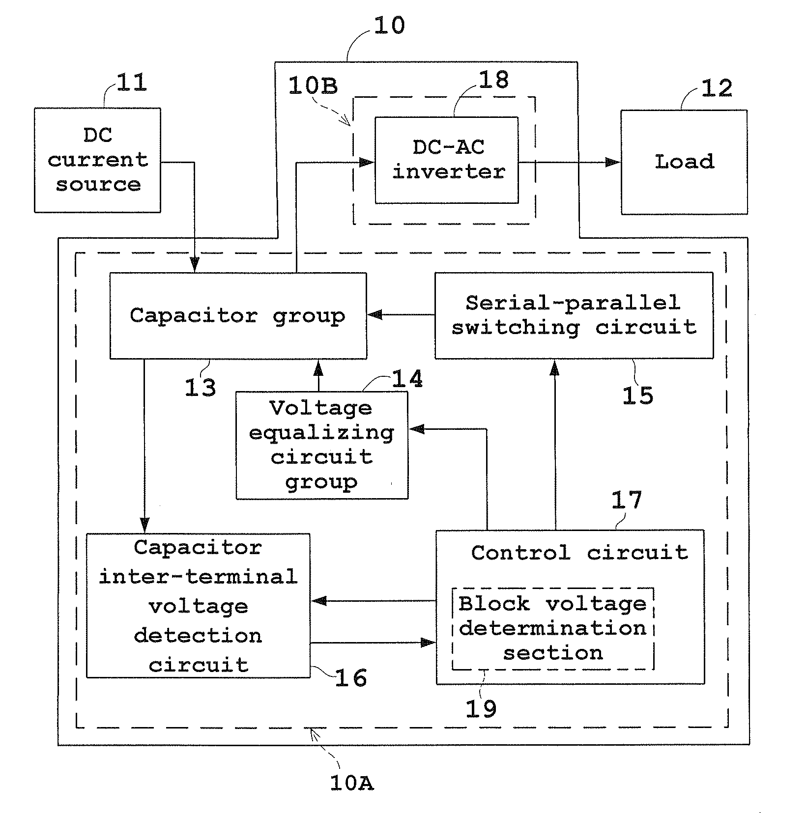
[0077]Embodiments of the present invention will be described below with reference to the drawings. FIG. 6 is a block diagram showing an embodiment of an electric power storage system using a capacitor (an electric double layer capacitor, for example) according to the present invention.

[0078]The electric power storage system of the present embodiment includes an electric power storage system body 10. The electric power storage system body 10 accumulates a DC electric power supplied from a DC current source 11, converts the accumulated electric power into an AC electric power, and supplies the AC electric power to a load 12.

[0079]The DC current source 11 being an external device is constituted of, for example, a solar cell, a wind power generator, an engine generator or the like.

[0080]The electric power storage system body 10 is roughly divided into an power storage unit 10A and a power inverter 10B which converts the DC electric power accumulated in the power storage unit 10A into an...


PUM


Abstract

In an electric power storage system according to the present invention, in the case of charging, a plurality of capacitors of each circuit block of the electric power storage system are switched to a serial connection to initiate the charging. When the output voltage of power storage means reaches the maximum input voltage of DC-AC conversion means, each capacitor of a number j of circuit blocks is switched to a parallel connection in order of higher block voltage. Also up to the time when the maximum input voltage is reached again, each capacitor of a number j of circuit blocks is switched to a parallel connection in order of higher block voltage. In the case of discharging, pluralities of capacitors of each circuit block of the electric power storage system are switched to a parallel connection to initiate the discharging. When the output voltage of power storage means reaches the minimum input voltage of DC-AC conversion means, each capacitor of a number k of circuit blocks is switched to a serial connection in order of higher block voltage. Also up to the time when the minimum input voltage is reached gain, each capacitor of a number k of circuit blocks is switched to a serial connection in order of higher block voltage. Accordingly, the electric power storage system is hardly affected by the capacitance error of the capacitors, and charging / discharging efficiency can be improved.

Description

TECHNICAL FIELD[0001]The present invention relates to an electric power storage system using capacitors such as electric double layer capacitors (EDLCs), and a control method of such an electric power storage system.BACKGROUND ART[0002]Recently, electric double-layer capacitors (EDLCs) have attracted an attention as new electric power storage device to take a place of secondary batteries due to the features such as a long cycle life and a wide working-temperature range. However, capacitors vary in output voltage in proportion to the electric charge stored, and the output voltage is low when using a single capacitor. Accordingly, it is common to use such capacitors by connecting more than one capacitor in series or in serial-parallel.[0003]A known method in order to supply a stable voltage to a load when capacitors are connected in series or in serial-parallel is such that a plurality of EDLCs are switched between series and serial-parallel using complex switches.[0004]In an electric...

Claims


Application Information

Patent Timeline
Patent Type & Authority Applications(United States)
IPC IPC(8): G05F1/00H02J7/00H01G11/00
CPCH02M3/07H02J7/0024H02J5/00
Inventor TAKEDA, HARUMITOYAMA, KAZUKI
Owner LIMITED COMPANY TM
Why Eureka
Try Eureka