
Circuit and method for programming charge storage memory cells

a charge storage and memory cell technology, applied in the field of nonvolatile memory, can solve the problems of difficult to predict the threshold voltage of the memory cell, time-consuming verification of operation, and inability to meet the requirements of memory cells in a large array, so as to achieve moderate hot electron injection efficiency and increase the effective threshold

Active Publication Date: 2005-08-30
MACRONIX INT CO LTD
View PDF14 Cites 142 Cited by
  • Summary
  • Abstract
  • Description
  • Claims
  • Application Information

AI Technical Summary

Benefits of technology

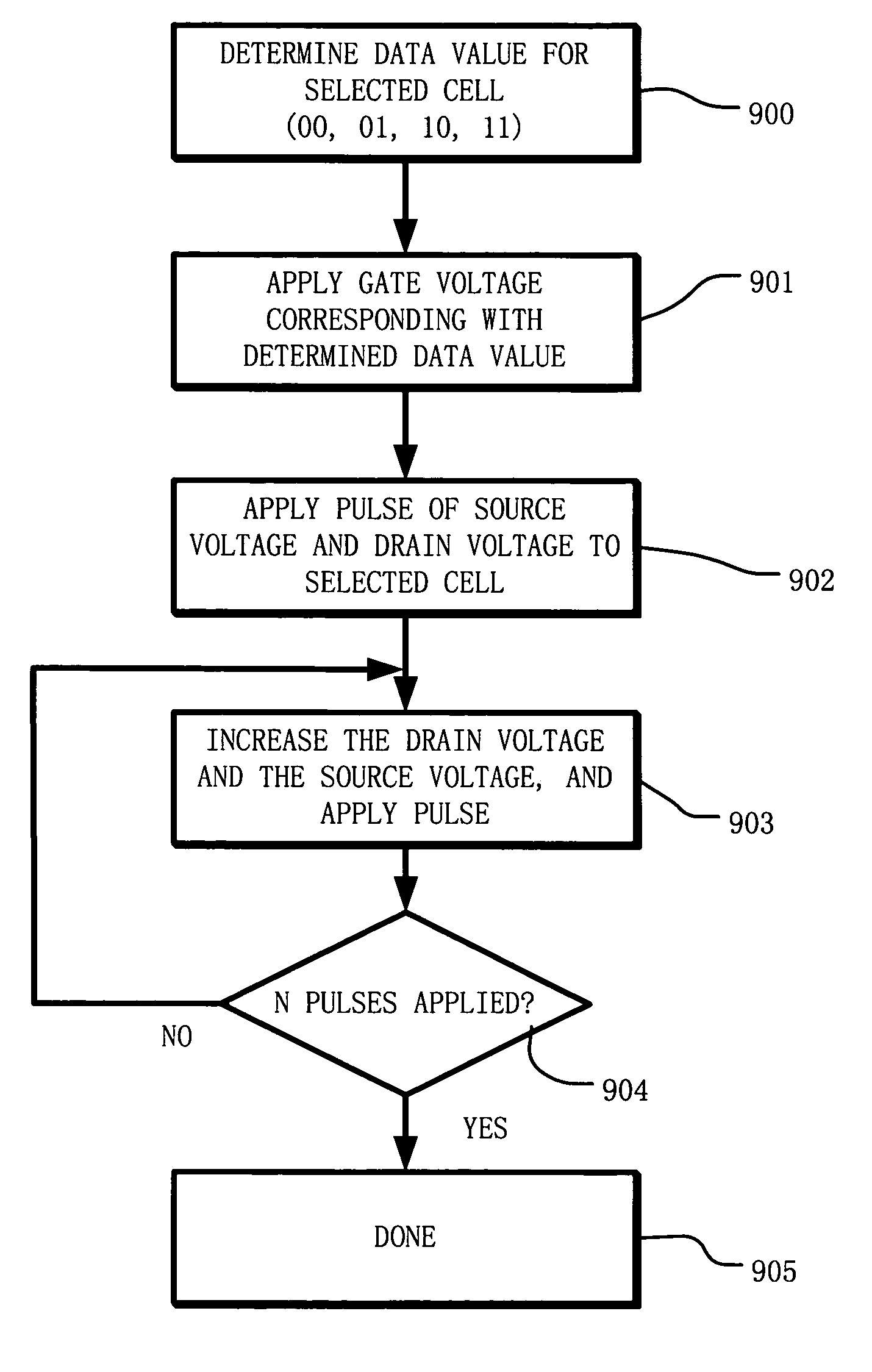
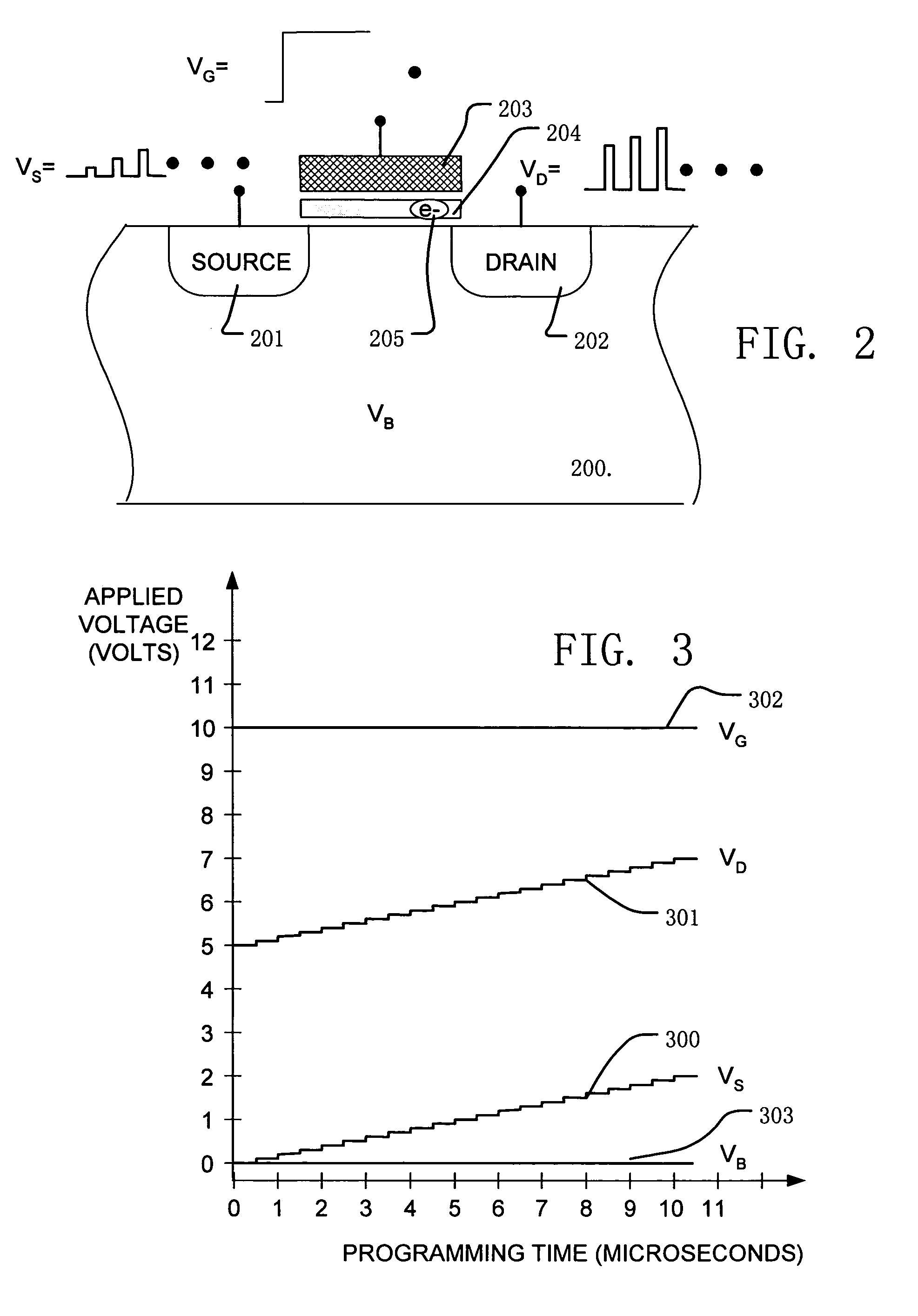
The present invention provides a method for programming a charge storage memory cell using hot electron injection. The method includes applying a source voltage to induce a body effect and increase the effective threshold, while increasing the drain voltage in equal steps to moderate hot electron injection efficiency. The method allows for self-convergence at more than one target threshold, without the need for verify operations. The method can be used for both single bit and multiple bit memory cells, and can program multiple data values in a cell. The invention also includes an integrated circuit memory and a program controller for executing the method. The technical effects of the invention include reducing the number of program pulses and programming times, avoiding over-programming, and allowing for multiple memory states in charge storage memory cells.

Problems solved by technology

One basic problem being addressed by these variations arises because the memory cells in a large array do not all behave uniformly during a programming operation.
The wide distribution of charge after a program pulse makes it difficult to predict the threshold voltage of the memory cell.
The verify operation is time-consuming, and requires complex program algorithms and supporting circuitry.

Method used


Image

  • Circuit and method for programming charge storage memory cells
  • Circuit and method for programming charge storage memory cells
  • Circuit and method for programming charge storage memory cells

Examples


Embodiment Construction

[0028]A detailed description of embodiments of the present invention is provided with reference to FIGS. 1–11.

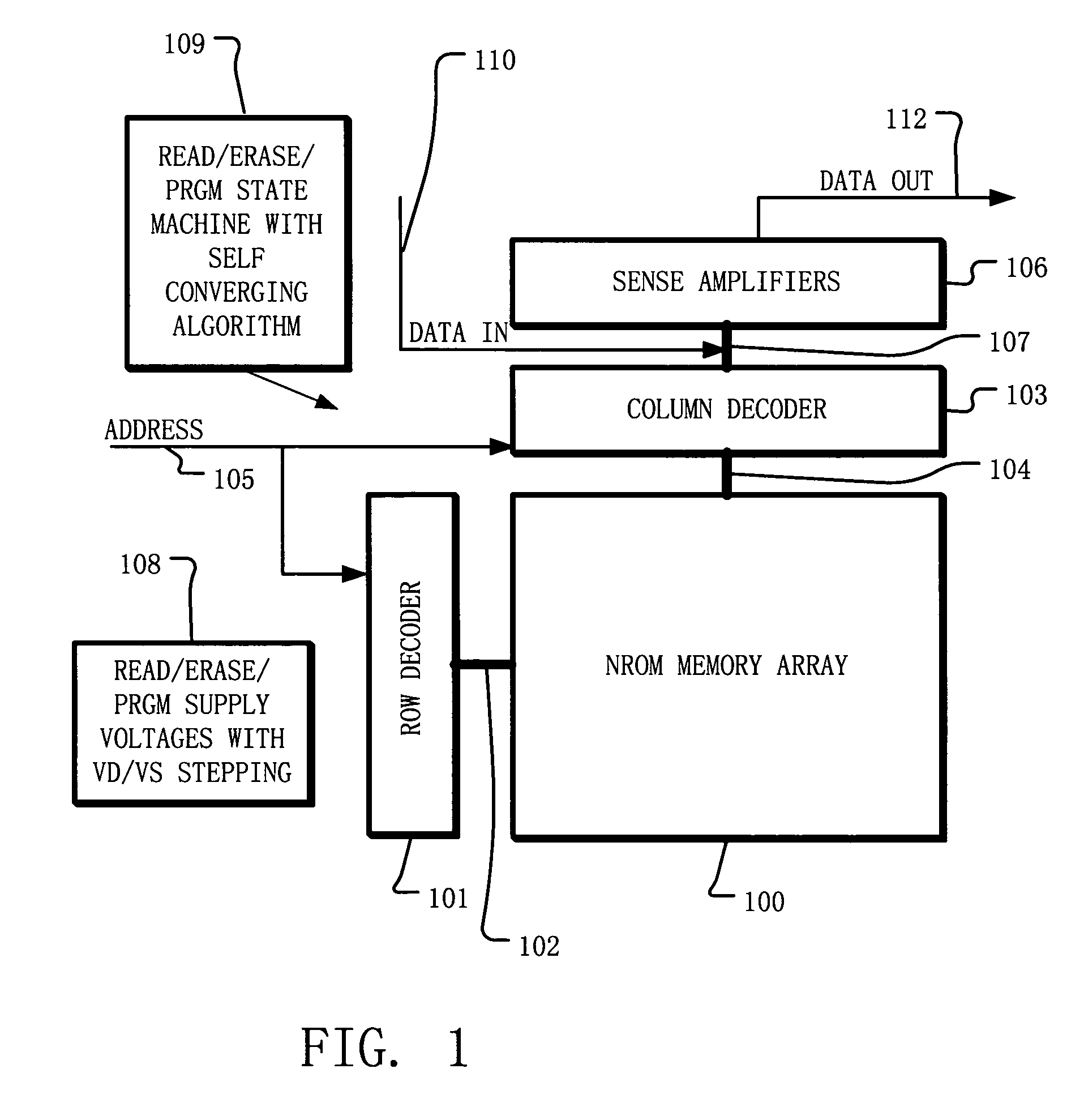
[0029]FIG. 1 is a simplified block diagram of an integrated circuit having sense amplifiers with latch timing control according to the present invention. The integrated circuit includes a memory array 100 implemented using NROM memory cells. Other embodiments use memory cells with charge storage elements other than a silicon nitride charge trapping layer, as used in an NROM cell, such as conductive floating gates as used in typical flash memory cells, and charge trapping layers comprising materials other than nitride. A row decoder 101, responsive to addresses on bus 105, is coupled to a plurality of word lines 102 arranged along rows in the memory array 100. A column decoder 103, responsive to addresses on line 105, is coupled to a plurality of bit lines 104 arranged along columns in the memory array 100. Addresses are supplied on bus 105 to column decoder 103 and row decod...


PUM


Abstract

A circuit and method for self-converging programming of a charge storage memory cell, such as NROM or floating gate flash, having a source and a drain in a substrate, a charge storage element and a control gate. The method includes applying source voltage, inducing a body effect that increases the effective threshold, and increasing the source voltage along with the drain voltage to moderate hot electron injection efficiency during the program operation, at least during a portion of the program operation in which convergence on a target threshold occurs. A selected gate voltage is applied during the operation to establish the target threshold voltage. In multiple bit cells, the gate voltage is set according to the data values to be stored, enabling self-convergence at more than one target threshold.

Description

BACKGROUND OF THE INVENTION[0001]1. Field of the Invention[0002]The present invention relates to non-volatile memory based on charge storage elements, such as NROM and floating gate flash memory, and to self-converging methods for programming single bit and multiple bit memory cells with target threshold voltages.[0003]2. Description of Related Art[0004]Non-volatile memories based on charge storage elements, including silicon-oxide-nitride-oxide-silicon SONOS-type cells and floating gate flash memory cells, are programmed by injecting charge into the charge storage element. The charge in the charge storage element affects the threshold voltage of the memory cell, and can be used for storing data.[0005]One basic technique used in many prior art devices to inject charge into the charge storage element is known as hot electron injection. Hot electron injection involves applying a high-voltage to a control gate on the memory cell, a high-voltage to the drain, and ground or a low-voltage...

Claims


Application Information

Patent Timeline
Patent Type & Authority Patents(United States)
IPC IPC(8): G11C11/56G11C11/34H01L21/70H01L21/8239H01L21/82H01L27/10H01L27/02G11C16/12G11C16/34H10B99/00
CPCG11C16/12G11C16/3459G11C16/3454
Inventor HSU, TZU-HSUANWU, CHAO-I
Owner MACRONIX INT CO LTD
Learn More