Power generator and power generation system

Active Publication Date: 2012-01-12
PANASONIC INTELLECTUAL PROPERTY MANAGEMENT CO LTD
View PDF3 Cites 152 Cited by
  • Summary
  • Abstract
  • Description
  • Claims
  • Application Information

AI Technical Summary

Benefits of technology

[0028]A power generator and power generation system according to a preferred embodiment of the present invention can increase the voltage significantly in transmitting power between antennas using magnetic resonant coupling. Also, a power generator and power generation system in accordance with other preferred embodiments of the present invention can transmit energy wirelessly by way of the space between the antennas (i.e., by a non-contact method). Thus, according to the present invention, the energy generated by a power generating section that is arranged outside of a building can be transferred to an electronic device inside of that building at an increased voltage. According to a preferred embodiment of the present invention, the cost of installing the power generat

Problems solved by technology

Use of such a solar power generation system, however, has not been widespread yet because the cost of manufacturing those cells and modules is too high, which is one of the major obstacles to its introduction.
On top of that, the cost of establishing such a system by installing those cells and modules is also too high to neglect.
Among other things, the higher the altitude of the place of installation, the riskier and the more expensive the installation work will be, which is a serious problem to overcome in order to further popularize the solar power generation system.
What is more, to introduce a solar power generation system into an existing building, it is difficult to install the wiring connecting the solar power generating section outside of the building to electronic devices inside of the building, which is also one of the big problems with conventional solar power generation systems.
And a decrease in reliability at such a very large number of connection points is a decisive factor in the decline of the long-term reliability of the overall system.
Consequently, the cost of maintenance is non-negligible, either.
The power supply system disclosed in

Method used


Image

  • Power generator and power generation system
  • Power generator and power generation system
  • Power generator and power generation system

Examples


embodiment 1

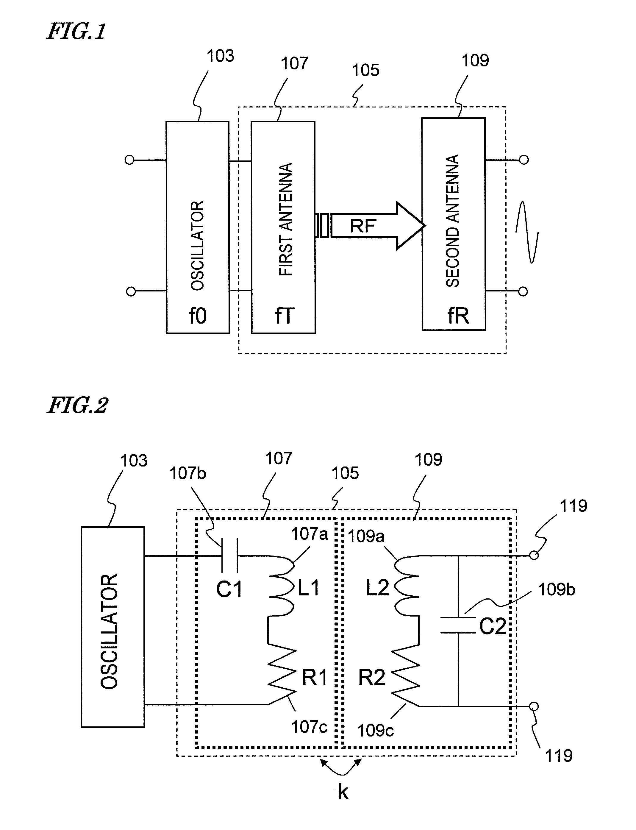
[0067]First of all, a First Specific Preferred Embodiment of a power generator according to the present invention will be described with reference to FIGS. 5 and 6. Specifically, FIG. 5 is a perspective view schematically illustrating the first preferred embodiment of the present invention and FIG. 6 is an equivalent circuit diagram of the wireless transmission section 105 shown in FIG. 5. In FIGS. 5 and 6, any component having substantially the same function as its counterpart shown in FIGS. 1 and 2 is identified by that counterpart's reference numeral.

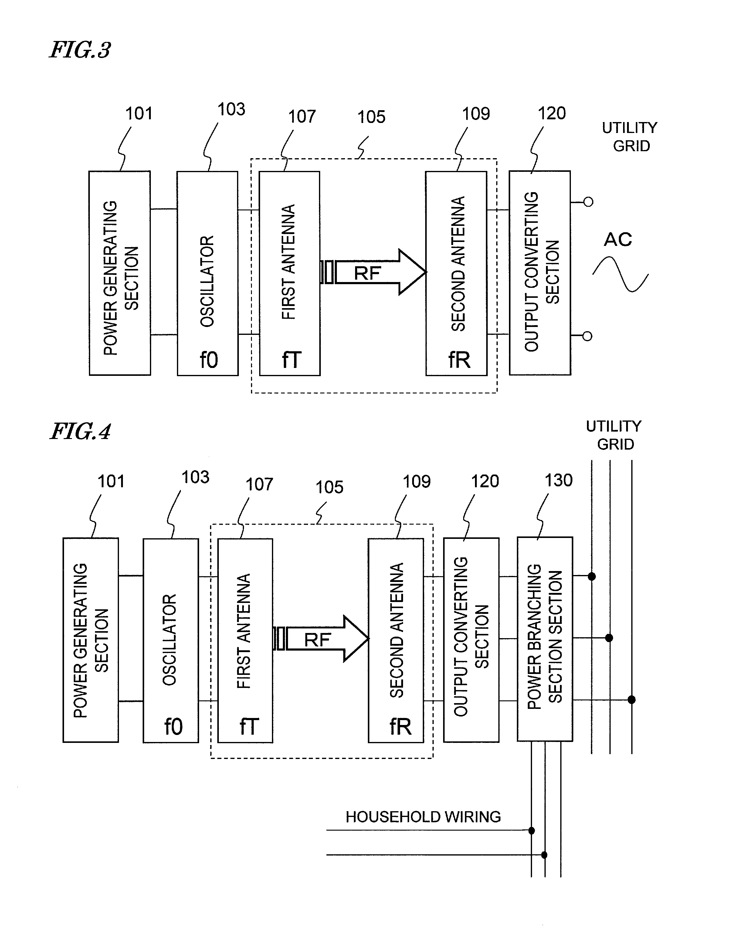
[0068]As shown in FIG. 5, the power generator of this preferred embodiment includes a power generating section 101, an oscillator 103, a wireless transmission section 105 and an output converting section 120, which are connected together in series.

[0069]In this preferred embodiment, the power generating section 101 includes a number of solar cells (which will be sometimes simply referred to herein as “cells”) that are connected toget...

embodiment 2

[0140]Hereinafter, a preferred embodiment of a power generation system according to the present invention will be described with reference to FIG. 14A, which is a block diagram illustrating a power generation system as a second specific preferred embodiment of the present invention. In FIG. 14A, any component having substantially the same function as its counterpart of the preferred embodiments described above is identified by that counterpart's reference numeral and the description thereof will be omitted herein to avoid redundancies.

[0141]The power generation system shown in FIG. 14A includes a number of power generating and voltage increasing sections 131a, 131b, . . . and 131n that are connected in parallel with each other. In this preferred embodiment, each of these power generating and voltage increasing sections 131a, 131b, . . . and 131n has the same configuration as a portion of the power generator of the first preferred embodiment that covers the range of the power generat...

example 1

[0152]Hereinafter, a first specific example of the present invention will be described.

[0153]First of all, nine single-crystal silicon based solar power generating elements (i.e., solar cells), of which the photosensitive plane had a square surface with a size of 12 cm each side, were connected together in series to obtain a solar power generating section with an output voltage of 4.5 V, an output current of 1 A, and an output impedance of 4.5Ω. And an oscillator with an output frequency of 3 MHz and an output impedance Zoc of 5Ω was connected to the output terminal of that solar power generating section. The oscillator, which was implemented as a class F amplifier, achieved an efficiency of 95%. In this first specific example, the oscillator has a voltage step-up ratio Vtr of 1.05.

[0154]The first and second antennas were designed so as to have a resonant frequency of 3 MHz, which was equal to the output frequency of the oscillator. Specifically, the first antenna was fabricated by ...


PUM


Abstract

A power generator according to the present invention includes: a power generating section (101) for outputting DC energy; an oscillator (103) for converting the DC energy into RF energy having a frequency f0; a first antenna (107) for transmitting the RF energy; a second antenna, which receives, by coupling a resonant magnetic field, at least a part of the RF energy transmitted by the first antenna (107); and an output converting section (120) for converting the RF energy supplied from the second antenna (109) into AC energy having a lower frequency than the RF energy. If the oscillator (103) has a voltage step-up ratio Voc, the output converting section (120) has a voltage step-up ratio Vtr, the first inductor (107a) of the first antenna (107) has an inductance L1, the second inductor (109a) of the second antenna (109) has an inductance L2, and the first and second antennas (107, 109) have a coupling coefficient k, the power generator satisfies (L2/L1)≧(k/(Voc×Vtr))2.

Description

[0001]This application claims priority under 35 USC §119(e) to U.S. Provisional Application No. 61 / 359,853 filed on Jun. 30, 2010, the entire contents of which are incorporated herein by reference.BACKGROUND OF THE INVENTION[0002]1. Field of the Invention[0003]The present invention relates to a magnetic resonant coupling power generator and power generation system for transmitting power wirelessly using magnetic resonant coupling instead of electromagnetic induction or electromagnetic wave propagation. More particularly, the present invention relates to a power generator and power generation system for raising the voltage of electric energy, which has been generated by a power generating section such as a solar cell, by magnetic resonant coupling wireless power transmission and outputting alternating current (AC) energy.[0004]2. Description of the Related Art[0005]A solar power generation system ordinarily uses a so-called “solar cell module” in which a very large number of solar ce...

Claims


Application Information

Patent Timeline
IPC IPC(8): H02J17/00H02J1/00
CPCH02J17/00H01F38/14H02J50/12H02J50/20
Inventor SADA, TOMOKAZUKANNO, HIROSHI
Owner PANASONIC INTELLECTUAL PROPERTY MANAGEMENT CO LTD
Why Eureka
Try Eureka