
Implantable devices using rechargeable zero-volt technology lithium-ion batteries

a technology of lithium-ion batteries and implantable devices, which is applied in the field of implantable pulse generators, can solve the problems of limited battery life, not all of the features of one device, and no one can teach the use of rechargeable zero-volt technology batteries within the implanted portion of the system, so as to ensure the safe and reliable operation of the system, simple connection, and high volumetric and gravimetric energy density

Inactive Publication Date: 2007-02-27
QUALLION +1
View PDF86 Cites 142 Cited by
  • Summary
  • Abstract
  • Description
  • Claims
  • Application Information

AI Technical Summary

Benefits of technology

[0018]In accordance with one aspect of the invention, therefore, a lithium-ion or lithium-ion polymer rechargeable battery is used in combination with appropriate battery protection and charging circuitry housed within an implantable medical device, e.g., an IPG, of a medical system, e.g., an SCS system. Such use of a rechargeable battery advantageously assures the safe and reliable operation of the system over a long period of time. While a preferred embodiment of the invention is represented and described herein by way of a spinal cord stimulation (SCS) system, it is to be emphasized that the invention—directed to the use of a lithium-ion or lithium-ion polymer rechargeable battery in an implanted medical device, including appropriate battery protection and battery charging circuitry—may be used within any implantable medical device.
[0019]The representative SCS system with which the lithium-ion based rechargeable battery is employed in accordance with the present invention provides multiple channels, each able to produce up to 20 mA of current into a 1 KΩ load. To provide adequate operating power for such a system, the SCS system employs a rechargeable battery and charging / protection system that allows the patient to operate the device independent of external power sources or controllers. Moreover, the implanted battery is rechargeable using non-invasive means, meaning that the battery can be recharged as needed when depleted by the patient with minimal inconvenience. Advantageously, the SCS system herein described requires only an occasional recharge, is smaller than existing implant systems, has a life of at least 10 years at typical settings, offers a simple connection scheme for detachably connecting a lead system thereto, and is extremely reliable.
[0020]A key element of the SCS system herein described (or other system employing an implantable pulse generator, or “IPG”) is the use of a rechargeable lithium-ion or lithium-ion polymer battery. Lithium-ion batteries offer several distinct advantages over other battery chemistries: high volumetric and gravimetric energy densities, high cell voltage, long cycle life, simple detection of charge termination, low toxicity, and no memory effect.
[0021]The lithium-ion or lithium-ion polymer battery used in the SCS system described herein is specifically designed for implantable medical devices. It incorporates several distinct features compared to conventional lithium-ion batteries. The battery case is made from a high-resistivity Titanium alloy to reduce heating from eddy currents induced from the electromagnetic field produced by inductive charging. The case is also hermetically-sealed to increase cycle life and shelf life performance. Most importantly, the battery is specifically designed to allow discharge to zero volts without suffering irreversible damage, which feature is referred to herein as “zero-volt technology”. This feature is significant because conventional lithium-ion batteries can not operate at low voltages (less than about 1 V) without damage occurring to the negative electrode. Thus, should an implant device with a conventional lithium-ion battery be operated until the implanted battery is nearly discharged (˜2.5 V), and if the battery is not subsequently recharged for any one of many reasons, the battery will naturally self-discharge to below 1 V in less than six months. If this occurs, the performance and safety of the cell may be compromised. In contrast, the present invention relates to an implantable electrical stimulator capable of recharging its lithium-ion battery from an electrical potential of 0 V up to normal operating voltages, e.g., approximately 4 V. The invention takes advantage of new battery technology that allows discharge down to 0 V without damage to the cell.
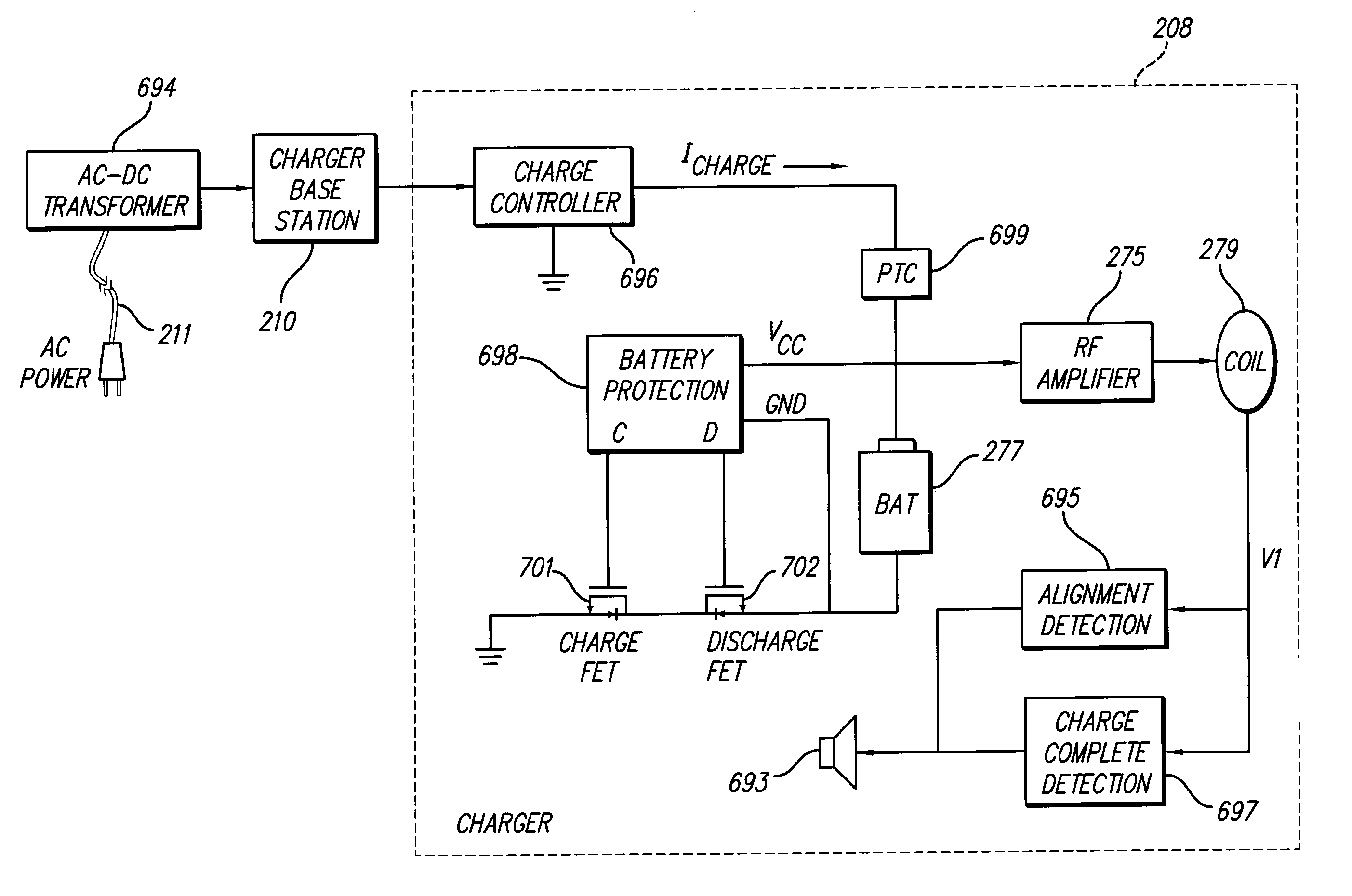
[0022]In accordance with one aspect of the present invention, the SCS system utilizes a non-invasive, electromagnetic induction system to couple the energy from an external power source to the implanted charging circuitry for recharging the battery. The charging circuitry contains a charge controller that converts the unregulated induced power into the proper charging current. The level of the charging current is determined by a state machine-type algorithm that monitors the voltage level of the battery. In one embodiment, when the battery voltage is below 1 V, for example, the battery is charged with a very low current of C / 50 ( 1 / 50 of the battery capacity) or less. When the battery voltage surpasses 1 V, the battery is charged at a rate of approximately C / 25. When the battery voltage surpasses 2.5 V, the battery is charged at the maximum charge rate of approximately C / 2, until the battery voltage nears its desired full-charge voltage, at which point the charge rate may again be reduced. That is, fast charging occurs at the safer lower battery voltages (e.g., voltage above about 2.5 V), and slower charging occurs when the battery nears full charge higher battery voltages (above about 4.0 V). When potentially less-than-safe very low voltages are encountered (e.g., less than 2.5 V), then very slow (trickle) charging occurs to bring the battery voltage back up to the safer voltage levels where more rapid charging can safely occur. This multi-rate charge algorithm minimizes charging time while ensuring the cell is safely charged. The charging circuitry also contains a battery protection circuit that continuously monitors the battery voltage and current. If the battery operates outside of a predetermined range of voltage or current, the battery protection circuitry disconnects the battery from the particular fault, i.e. charging circuitry or load circuits. Moreover, the charging circuitry is able to monitor the state-of-charge of the battery by measuring the voltage of the battery, since there is good correlation between battery voltage and state of charge in lithium-ion batteries.
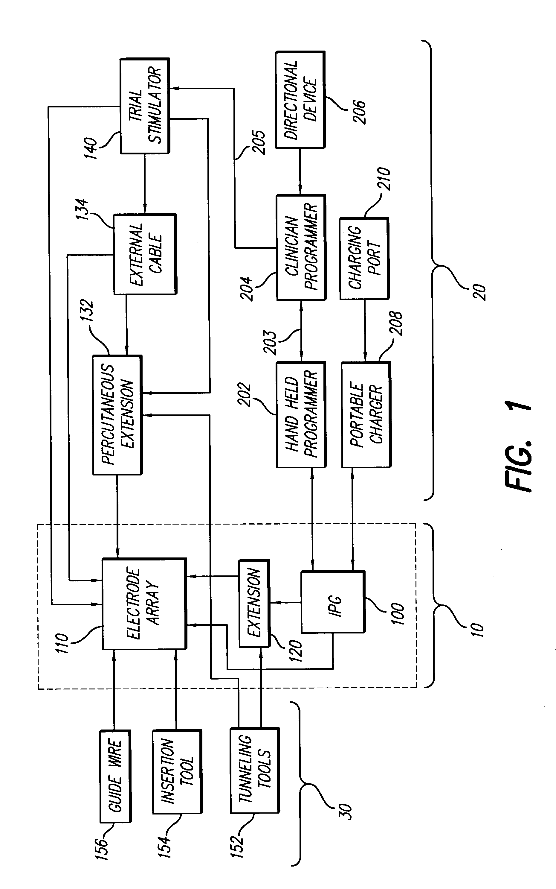
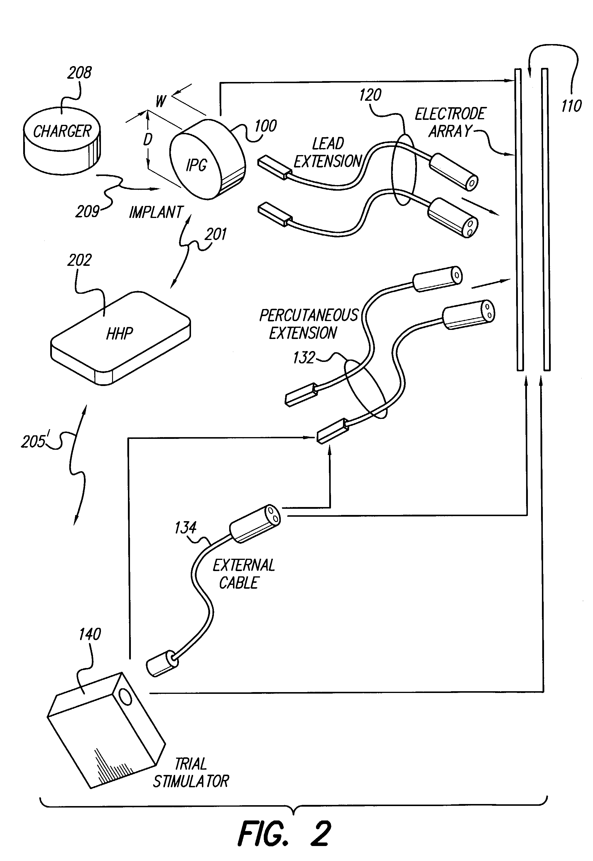
[0025]In operation, the SCS system (or other system employing an IPG) monitors the state of charge of the internal battery and controls the charging process. Then, through a suitable communication link, the SCS system is able to inform the patient or clinician regarding the status of the system, including the state of charge, and makes requests to initiate an external charge process. In this manner, the acceptance of energy from the external charger is entirely under the control of the implant circuitry, e.g., the IPG, and several layers of physical and software control may be used, as desired or needed, to ensure reliable and safe operation of the charging process. The use of such a rechargeable power source thus greatly extends the useful life of the SCS system, or other IPG systems. This means that once the IPG is implanted, it can, under normal conditions, operate for many years without having to be explanted.

Problems solved by technology

Spinal cord and other stimulation systems are known in the art, however, to applicants' knowledge, none teach the use of a rechargeable zero-volt technology battery within the implanted portion of the system, with accompanying charging and protection circuitry, as proposed herein.
Unfortunately, not all of these features are available in any one device.
For example, one known device has a limited battery life at only modest current outputs, and has only a single voltage source, and hence only a single stimulation channel (programmable voltage regulated output source), which provides a single fixed pattern to up to four electrode contacts.
Another known device offers higher currents that can be delivered to the patient, but does not have a battery, and thus requires the patient to wear an external power source and controller.
Yet a third known device provides multiple channels of modest current capability, but does not have an internal power source, and thus also forces the patient to wear an external power source and controller.
However, devices powered by primary (non-rechargeable) batteries have a finite lifetime before the device must be surgically removed and replaced.
Frequent surgical replacement is not an acceptable alternative for many patients.
Powering these devices with conventional primary batteries would require considerably larger capacity batteries to operate them for a reasonable length of time, resulting in devices so large that they may be difficult to implant or, at the very least, reduce patient comfort.
However, given the state of the art in battery technology, the required energy density is not achievable at the present time.
However, these systems obviously require the patient to continually wear an external device to power the implanted pulse generator, which may be unacceptable for many patients because they are often bulky and uncomfortable to wear, and naturally, limit patient mobility.
However, these devices were met with limited success in regards to battery performance and market acceptance.
NiCd's low volumetric energy density of 100 Wh / liter provided limited energy storage, and frequent charging was required.
NiCd batteries also suffered from a phenomenon called “memory effect,” which causes the cell to lose capacity if cycled at shallow discharge depths.
Moreover, NiCd batteries have a high self-discharge rate, losing approximately 30% of their capacity per month at body temperatures.
Also, cycle life performance was poor, as NiCd batteries typically lasted fewer than 300 cycles.
In addition, charging NiCd batteries was often problematic because the standard charge termination method for NiCd batteries is somewhat complicated, requiring the need to detect a zero or negative voltage slope (dV / dt) and / or temperature slope (dT / dt).
Cell leakage or venting can occur as a result of the pressure increase in the cell.
Furthermore, there may be disposal issues with NiCd batteries, as cadmium is highly toxic to the environment.
However, NiMH batteries suffer from some of the same drawbacks as well, including low cell voltage (1.2 V), high self-discharge (>30% per month), difficult charge termination, low cycle life (<300 cycles), and to a lesser extent, memory effect.
However, lithium metal in its pure form is extremely reactive, and proved to be very unstable as a battery electrode as employed in early designs.
However, Lithium-ion batteries are not as tolerant to overcharging and overdischarging.
As a result, cell leakage or venting can occur.
If Lithium-ion batteries are over-discharged (<1 V), the negative electrode may dissolve and cause plating of the electrodes.
This can lead to internal shorts within the cell, as well as possible thermal runaway.
However, such disclosed use requires careful avoidance of overcharge and overdischarging conditions, as outlined above, else the implant battery, and hence the implant device, is rendered useless.
Unfortunately, commercial realization of Lithium-ion polymer batteries has been slow and fraught with early production problems.

Method used


Image

  • Implantable devices using rechargeable zero-volt technology lithium-ion batteries
  • Implantable devices using rechargeable zero-volt technology lithium-ion batteries
  • Implantable devices using rechargeable zero-volt technology lithium-ion batteries

Examples


Embodiment Construction

[0041]The following description is of the best mode presently contemplated for carrying out the invention. This description is not to be taken in a limiting sense, but is made merely for the purpose of describing the general principles of the invention. The scope of the invention should be determined with reference to the claims.

[0042]At the outset, it is noted that the present invention may be used with an implantable pulse generator (IPG), or similar electrical stimulator and / or electrical sensor, that may be used as a component of numerous different types of stimulation systems. The description that follows relates to use of the invention within a spinal cord stimulation (SCS) system. However, it is to be understood that the invention is not so limited. Rather, the invention may be used with any type of implantable electrical circuitry that could benefit from deriving its operating power from a rechargeable battery.

[0043]Further, while the invention is described in connection wit...


PUM


Abstract

An implantable medical device, such as an implantable pulse generator (IPG) used with a spinal cord stimulation (SCS) system, includes a rechargeable lithium-ion battery having an anode electrode with a substrate made substantially from titanium. Such battery construction allows the rechargeable battery to be discharged down to zero volts without damage to the battery. The implantable medical device includes battery charging and protection circuitry that controls the charging of the battery so as to assure its reliable and safe operation. A multi-rate charge algorithm is employed that minimizes charging time while ensuring the battery cell is safely charged. Fast charging occurs at safer lower battery voltages (e.g., battery voltage above about 2.5 V), and slower charging occurs when the battery nears full charge higher battery voltages (e.g., above about 4.0 V). When potentially less-than-safe very low voltages are encountered (e.g., less than 2.5 V), then very slow (trickle) charging occurs to bring the battery voltage back up to the safer voltage levels where more rapid charging can safely occur. The battery charging and protection circuitry also continuously monitors the battery voltage and current. If the battery operates outside of a predetermined range of voltage or current, the battery protection circuitry disconnects the battery from the particular fault, i.e. charging circuitry or load circuits.

Description

[0001]This application is a continuation-in-part (CIP) of U.S. application Ser. No. 09 / 627,803, filed Jul. 28, 2000, now U.S. Pat. No. 6,553,263 which application claims the benefit of U.S. Provisional Application Ser. No. 60 / 146,571, filed Jul. 30, 1999, which applications are incorporated herein by reference.BACKGROUND OF THE INVENTION[0002]The present invention relates generally to implantable pulse generators, e.g., a pulse generator used within a Spinal Cord Stimulation (SCS) system or other type of neural stimulation system. More particularly, the present invention relates to the use of a rechargeable zero-volt technology lithium-ion battery within such an implantable pulse generator.[0003]Implantable pulse generators (IPG) are devices that generate electrical stimuli to body nerves and tissues for the therapy of various biological disorders, such as pacemakers to treat cardiac arrhythmia, defibrillators to treat cardiac fibrillation, cochlear stimulators to treat deafness, re...

Claims


Application Information

Patent Timeline
Patent Type & Authority Patents(United States)
IPC IPC(8): A61N1/18A61N1/08A61N1/34
CPCA61N1/36071A61N1/08A61N1/3787
Inventor MEADOWS, PAUL MWOODS, CARLA MANNCHEN, JOEYTSUKAMOTO, HISASHI
Owner QUALLION
Learn More