
Automated transaction machine and method

a transaction machine and automatic technology, applied in the field of automatic transaction machines and methods, can solve the problems of inconvenient connection, inconvenient installation, and laboriousness, and achieve the effect of convenient connection

Inactive Publication Date: 2001-08-16
DIEBOLD NIXDORF
View PDF0 Cites 249 Cited by
  • Summary
  • Abstract
  • Description
  • Claims
  • Application Information

AI Technical Summary

Benefits of technology

[0014] It is an object of the present invention to provide an ATM in which transaction devices may be more easily connected.
[0015] It is an object of the present invention to provide an ATM in which the amount of time it takes to add a transaction function device to the ATM is reduced.
[0016] It is a further object of the present invention to provide an ATM in which the possibility of installing a wrong driver for a device in the ATM is reduced.

Problems solved by technology

However, if the new device is so substantially changed relative to a device that it replaces so that it requires an updated driver, a service technician will be required to install a new device driver with the new device.
Unfortunately installing new drivers can require more time than installing a new physical transaction function device in the ATM.
Keeping track of the correct drivers and verifying that the correct driver is installed for a device, is a tedious endeavor.
Furthermore it may not be obvious when a driver for "Model A" of a device is incorrectly used for "Model B".
Although 99% of the functionality of the device may work properly, an ATM with an incorrect driver may experience intermittent problems related to that 1% of incompatibility with the driver.
Tracking down these incompatibilities can consume a large amount of a technician's time.
However, if a device is disabled, prior art ATMs may not notice that the device is disabled until the ATM attempts to use the device, at which time an error is generated.
Such an error usually results in the entire ATM or system being disabled until the device is reenabled or the ATM is manually reconfigured to know that the device is no longer available.
Consequently, changes to the configuration of an ATM require disabling the ATM for a period of time to remove, replace or add a device.
This process can be time consuming and may result in lost business at the ATM.
Individual devices often do not control the functionality of other devices.
The additional code required makes the application program more complex and more difficult to modify.
This low level complexity often makes ATM application programs more complex and difficult to produce and reconfigure.
Such device buses limit the number of devices that can be attached to an ATM and limit the physical locations at which devices can be attached.

Method used


Image

  • Automated transaction machine and method
  • Automated transaction machine and method
  • Automated transaction machine and method

Examples


Embodiment Construction

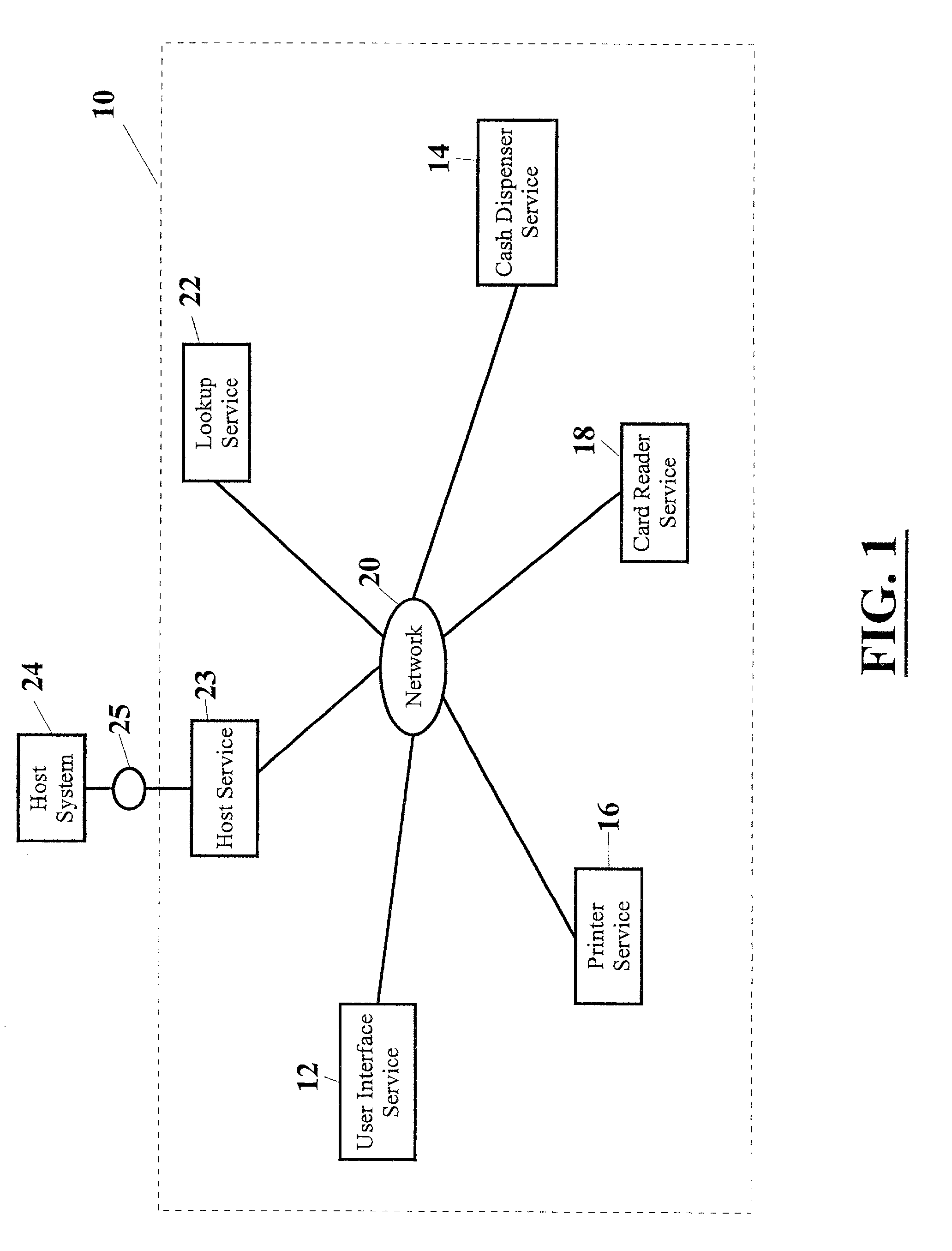
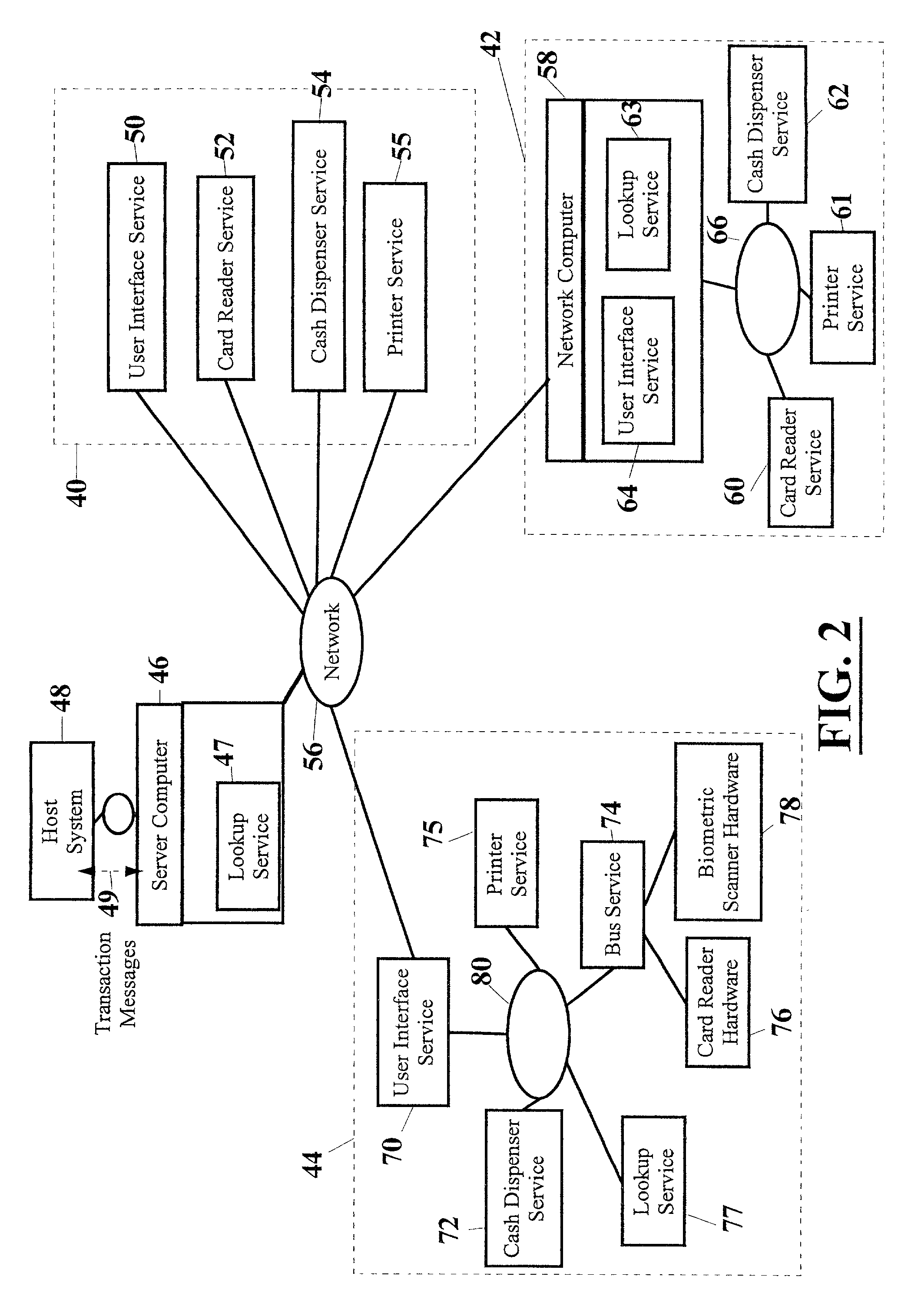
[0097] Referring now to the drawings and particularly to FIG. 1, there is shown therein, a schematic view of an ATM 10 that includes a number of transaction services, including an application 12 which is referred to herein as a user interface service. The exemplary ATM further includes a cash dispenser service 14, a print service 16, and a card reader service 18. Each of these services is connected to a common network 20. The ATM also includes a lookup service 22 that is responsible for registering new services on the network and providing a repository of service proxies of the services connected to the network.

[0098] The ATM also includes a host service 23 that is operative to pass transaction messages between the ATM and an external network 25. Network 25 is connected to at least one host system 24 and preferably a plurality of host systems used in connection with banking systems or clearinghouses. Host system 24 is typically responsible for transaction processing related to such ...


PUM


Abstract

A system for connecting transaction services to an ATM (10, 500) that includes a network (20). A user interface service (12) and a lookup service (22) are in operative connection with the network. Transaction services such as a printer service (16), card reader service (18), and cash dispenser service (14) are also in operative connection with the network. These transaction services are operative to register with the lookup service and to upload a service proxy to the lookup service. The user interface service is operative to locate transaction services on the network by invoking a remote lookup method on the lookup service. The lookup service is operative to return service proxies that match the type of service that is required. The user interface service is further operative to invoke methods of the service proxies that remotely control the functionality of the transaction services on the network. The user interface service is further operative to register events with the service proxies for notification when certain events on the services occur.

Description

[0001] This invention relates to the connection of devices in automated transaction machines. Specifically this invention relates to a new method and system for connecting transaction services in automated transaction machines.[0002] Automated transaction machines are known in the prior art. Automated transaction machines are used to electronically carry out transfers representative of value. Automated transaction machines include for example, cash dispensers, ticket dispensers, scrip dispensers, gaming machines, Automated Teller Machines (ATMs) and other self service terminals. For purposes of convenience all such automated transaction machines will be referred to herein as ATMs unless otherwise specifically indicated.[0003] ATMs may include various types of transaction function devices. These devices are operated to carry out transactions. Different types of ATMs include different types of devices. The different types of devices enable the ATM to carry out different types of trans...

Claims


Application Information

Patent Timeline
Patent Type & Authority Applications(United States)
IPC IPC(8): G06Q20/10G06F19/00G06Q40/00G07F19/00
CPCG06F9/548G06Q20/102G06Q20/1085G06Q40/00G06Q40/025G06Q40/04G07F19/20G07F19/201G07F19/211G06Q40/03
Inventor DRUMMOND, JAY PAULCICHON, BOBSMITH, MARKBLACKSON, DALEWEIS, DAVIDCHURCH, JAMES R.GILGER, MIKAL R.
Owner DIEBOLD NIXDORF
Learn More