
Medical instrument

a technology for medical devices and inserts, applied in the field of medical devices, can solve the problems of awkward assembly and user inability to recognize directly, and achieve the effect of easy recognition of the operation readiness of the instrument and simple connection of the instrument inserts

Active Publication Date: 2012-02-14
RICHARD WOLF GMBH
View PDF5 Cites 242 Cited by
  • Summary
  • Abstract
  • Description
  • Claims
  • Application Information

AI Technical Summary

Benefits of technology

The invention is a medical instrument that allows for easier connection and disconnection of different instruments with the same handle. This is achieved by using a detachable instrument insert and a movable grip that can be connected and disconnected easily. The instrument insert has an actuation rod that is connected to the grip, and a blocking element that automatically holds the grip in a defined position when the actuation rod is detached. This allows for a simpler and more secure connection of the instrument insert to the handle. The instrument handle has a receiver for the actuation rod, which is held in a predefined position, and the actuation rod can be easily connected again. The connection between the actuation rod and the grip is preferably designed as a ball locking connection, which allows for easy assembly and rotation of the instrument insert. The invention provides an improved medical instrument that allows for easier handling and operation.

Problems solved by technology

The assembly is therefore awkward, and the user may not directly recognize whether both connections are securely locked and the functioning ability of the instrument is ensured.

Method used


Image

  • Medical instrument
  • Medical instrument
  • Medical instrument

Examples


Embodiment Construction

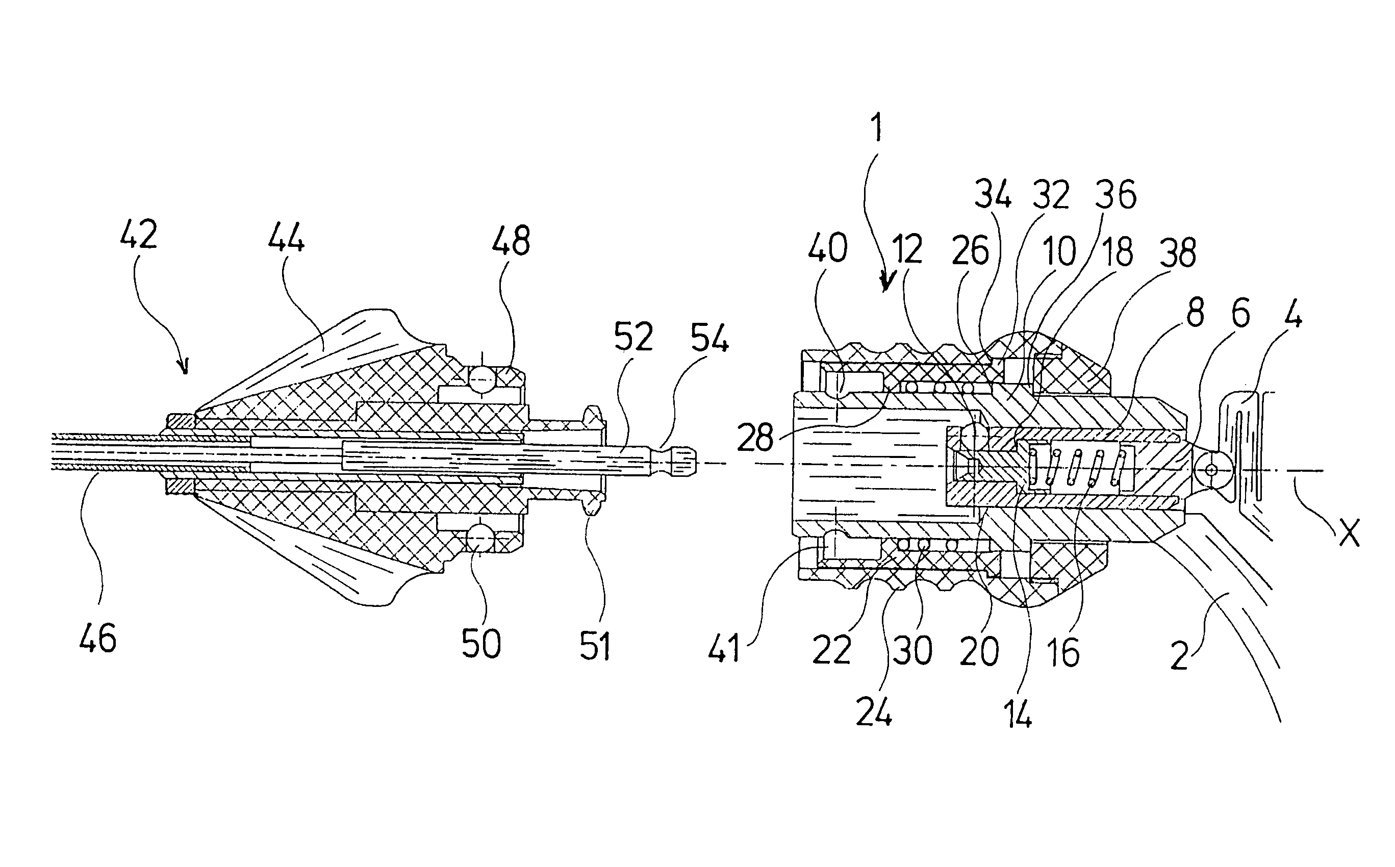
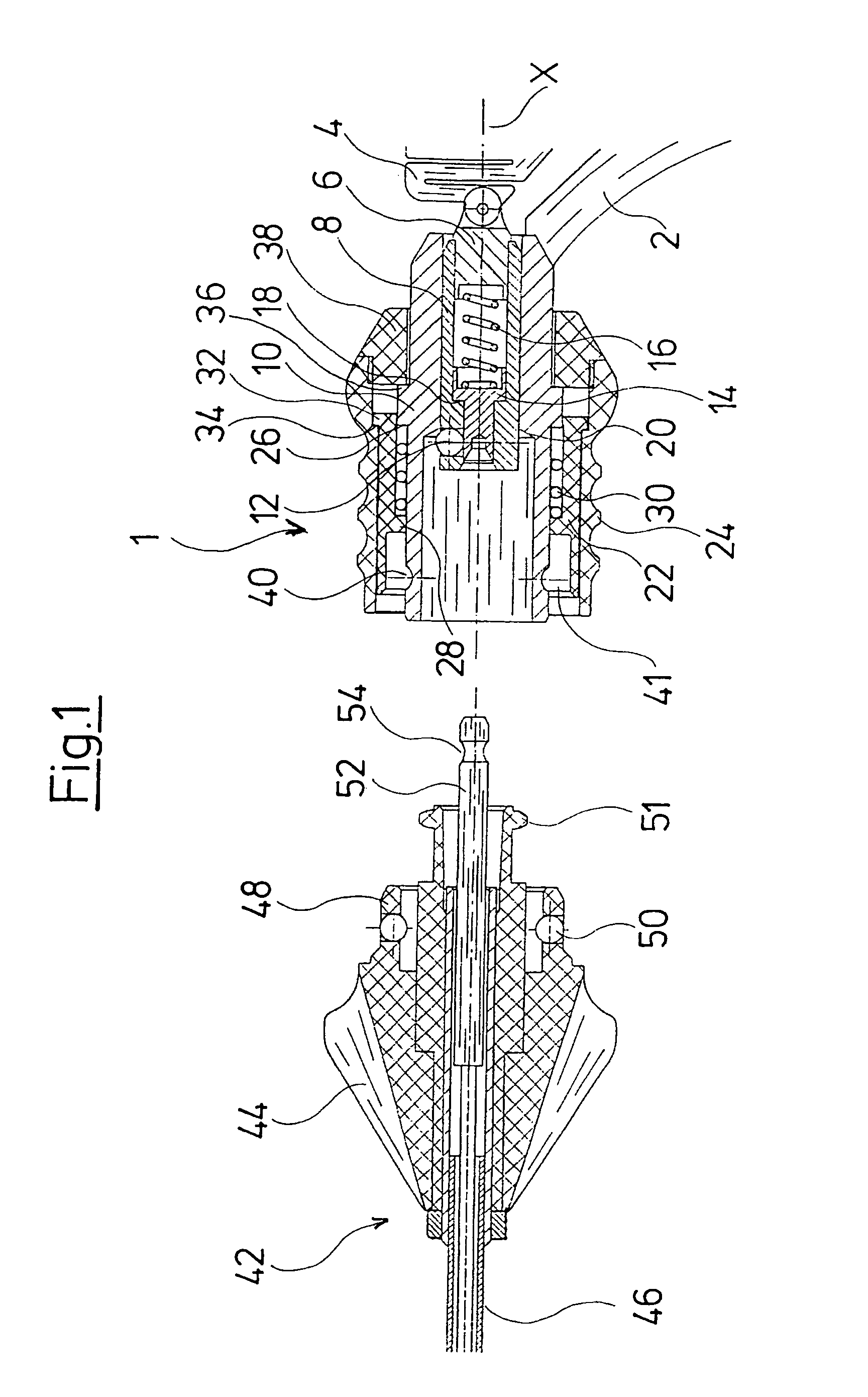
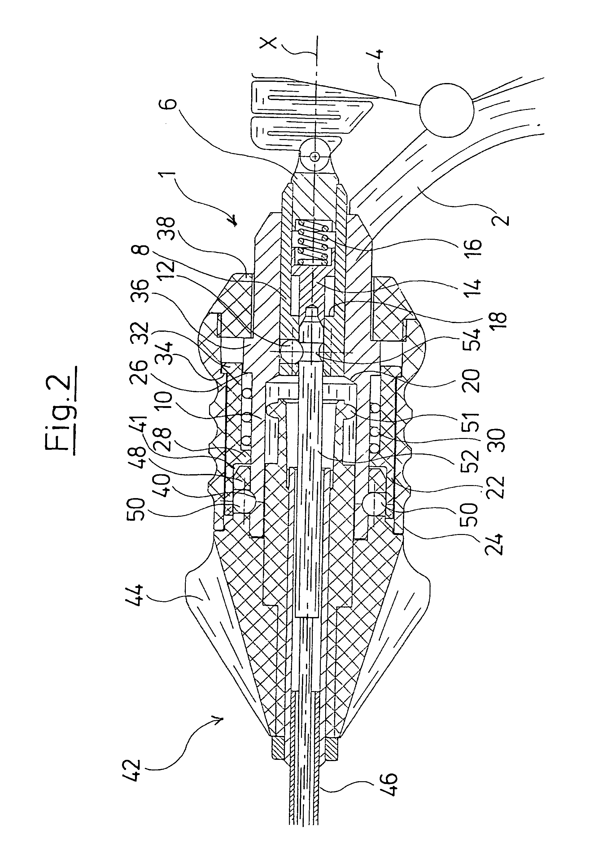
[0037]A first preferred embodiment of the invention is explained by way of FIGS. 1 and 2. FIG. 1 shows the distal end of an instrument handle 1, for example a forceps handle, as well as the proximal end of an instrument insert, for example a forceps insert, in section. The instrument handle comprises a fixed grip 2 and a movable grip 4 (both shown in fragment), with the movable grip being connected to a cylinder sleeve 8 via a connection part 6. The movable grip 4 is pivotally attached to the instrument handle 1, such that the movable grip 4 is movable along an arc extending tangentially to a longitudinal axis X of the instrument. The connection part 6 is firmly connected to the cylinder sleeve 8. The cylinder sleeve 8 is movably guided in the direction of the instrument longitudinal axis X in a cylinder receiver 10, which is firmly connected to the fixed grip 2. Radially outwardly directed through-bores are arranged in the region of the distal end of the cylinder sleeve 8, in which...


PUM


Abstract

A medical instrument has an instrument insert and an instrument handle, which are detachably connected to one another. An actuation rod of the instrument insert is releasably connectable to a movable grip of the instrument handle via a locking connection. A blocking element is provided which blocks the movable grip when the actuation rod has been released.

Description

BACKGROUND OF THE INVENTION[0001]The invention relates to a medical instrument and in particular to a medical forceps.[0002]A surgical tubular shank instrument is known for example from German Patent DE 198 09 120 C1, which comprises a grip part and a shank which is detachably connectable to the grip. An actuation rod is movably arranged in the shank in order to be able to move parts, for example a forceps jaw at the distal end of the shank, via a movable hand grip on the grip part. The shank and the actuation rod are connected via ball locking connections to the grip or to an actuation rod arranged in this. For complete connection of the shank and the actuation rod to the grip, two ball-locking connections thus need to be locked. The assembly is therefore awkward, and the user may not directly recognize whether both connections are securely locked and the functioning ability of the instrument is ensured.BRIEF SUMMARY OF THE INVENTION[0003]It is therefore an object of the invention ...

Claims


Application Information

Patent Timeline
Patent Type & Authority Patents(United States)
IPC IPC(8): A61F17/00B25G3/02B23B31/02A61B17/00A61B17/28
CPCA61B17/29A61B17/2909A61B2017/0046A61B2017/00464Y10T279/20A61B2017/292A61B2017/2931Y10T279/17752Y10T279/17811A61B2017/00477
Inventor KNODEL, FRANKPRESTEL, STEPHANWAGNER, CARL-SEBASTIANBARTOLIC, JOSEF
Owner RICHARD WOLF GMBH
Learn More