

Method and device for limiting the ageing of fuel cells with proton exchange membrane
a fuel cell and proton exchange membrane technology, applied in the direction of fuel cells, solid electrolyte fuel cells, electrochemical generators, etc., can solve the problems of fuel cell use and development for the consumer market, hydrogen is not enough to reach the oxygen level, degradation is worsening,
- Summary
- Abstract
- Description
- Claims
- Application Information
AI Technical Summary
Benefits of technology
Problems solved by technology
Method used
Image

Examples
Embodiment Construction
[0084]A fuel cell consisting of MEA 1 having an active surface area (Pt catalyst) of 2 cm2 supplied with pure hydrogen and oxygen which operates at 1.5 bar at the anode (H2) and at 80° C. and 100% RH at the cathode (O2).
[0085]An on (45 minutes) / off (15 minutes) load cycle is adopted.
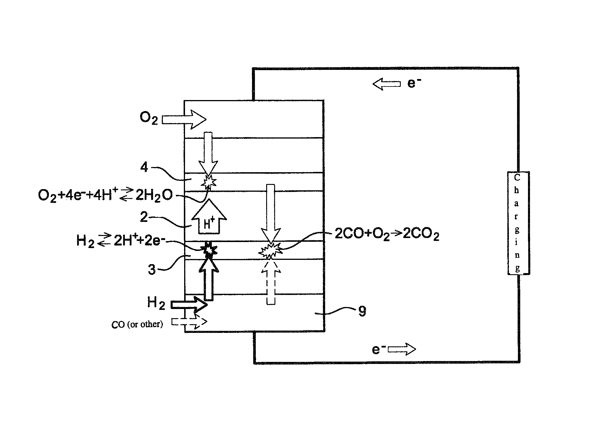
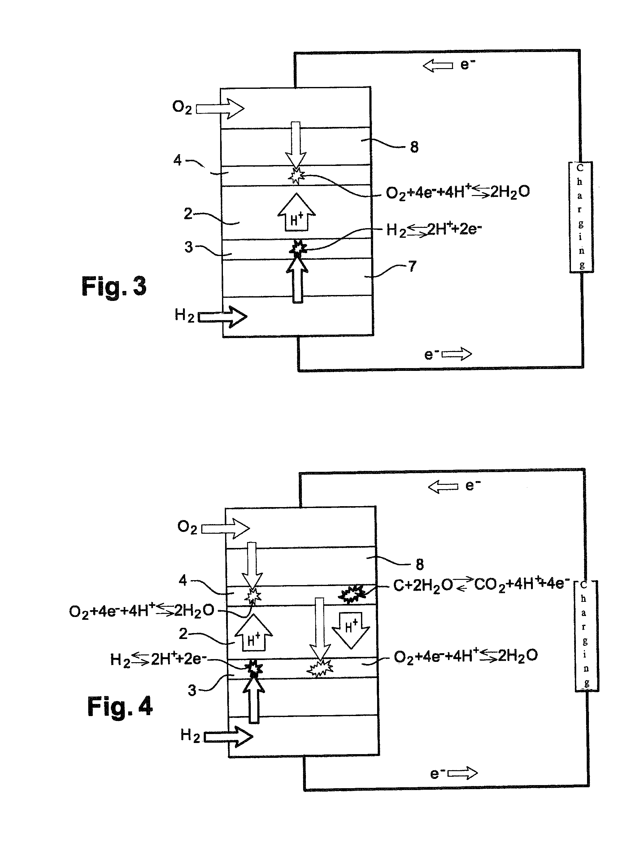
[0086]When the concentration of oxygen at anode 3, due to crossover, is of the order of 1 ppm, it has been found that up to 50% of cathodic carbon support 4 can be lost after roughly 1000 hours of operation.
[0087]Under these conditions, approximately 2 ppm of CO was supplied at anode 3 via channels 9 which make it possible to feed in hydrogen. The gas exchanges and reactions which take place under these conditions inside the PEMFC fuel cell are shown in FIG. 7A.
[0088]Measurements reveal that the corrosion of cathodic carbon 4 and degradation of proton conductors (2, 3, 4) were thus limited.
[0089]Firstly, the mass of carbon lost is reduced to approximately 30% after 1000 hours of operation. Secondly, x-ra...
PUM
| Property | Measurement | Unit |
|---|---|---|
| voltages | aaaaa | aaaaa |
| RH | aaaaa | aaaaa |
| active surface area | aaaaa | aaaaa |
Abstract
Description
Claims
Application Information