Cyclone separating apparatus of vacuum cleaner

a vacuum cleaner and cyclone technology, applied in the direction of dispersed particle separation, cleaning equipment, separation processes, etc., can solve the problem of a small volume of the primary dust chamber, and achieve the effect of longer sucking of dust and constant sucking

Inactive Publication Date: 2015-05-19
YUYAO JINGCHENG HIGH & NEW TECH
View PDF3 Cites 8 Cited by
  • Summary
  • Abstract
  • Description
  • Claims
  • Application Information

AI Technical Summary

Benefits of technology

[0004]The present invention is to provide a multi-cyclone separating apparatus of vacuum cleaner having high efficiency of dust separating and strong ability of continuous dust suction.
[0006]In a preferred embodiment, the lower part of the downstream cyclone forms a cone tapering from top to bottom, and the lower part of the downstream cyclone is arranged beside the upstream cyclone while the upper part is located above the upstream cyclone, which makes the distribution of inner parts of the separating apparatus more reasonable and the inner structure more compact.
[0009]In some certain embodiments, the undersurface of the downstream cyclone is inclined in such a way that it inclines downward from the near to the distant to the longitudinal axis of the shielding cover. The downstream dust hole is opened on the inclined undersurface of the downstream cyclone. The inclination of the undersurface makes the downstream dust hole incline towards the longitudinal axis of the secondary dust chamber, which makes the dust separated by the downstream cyclone be rejected along a direction towards the inside of the shielding cover to improve the dust separating efficiency.

Problems solved by technology

The problem of this establishment is that the volume of primary dust chamber is rather small.

Method used


Image

  • Cyclone separating apparatus of vacuum cleaner
  • Cyclone separating apparatus of vacuum cleaner
  • Cyclone separating apparatus of vacuum cleaner

Examples


Embodiment Construction

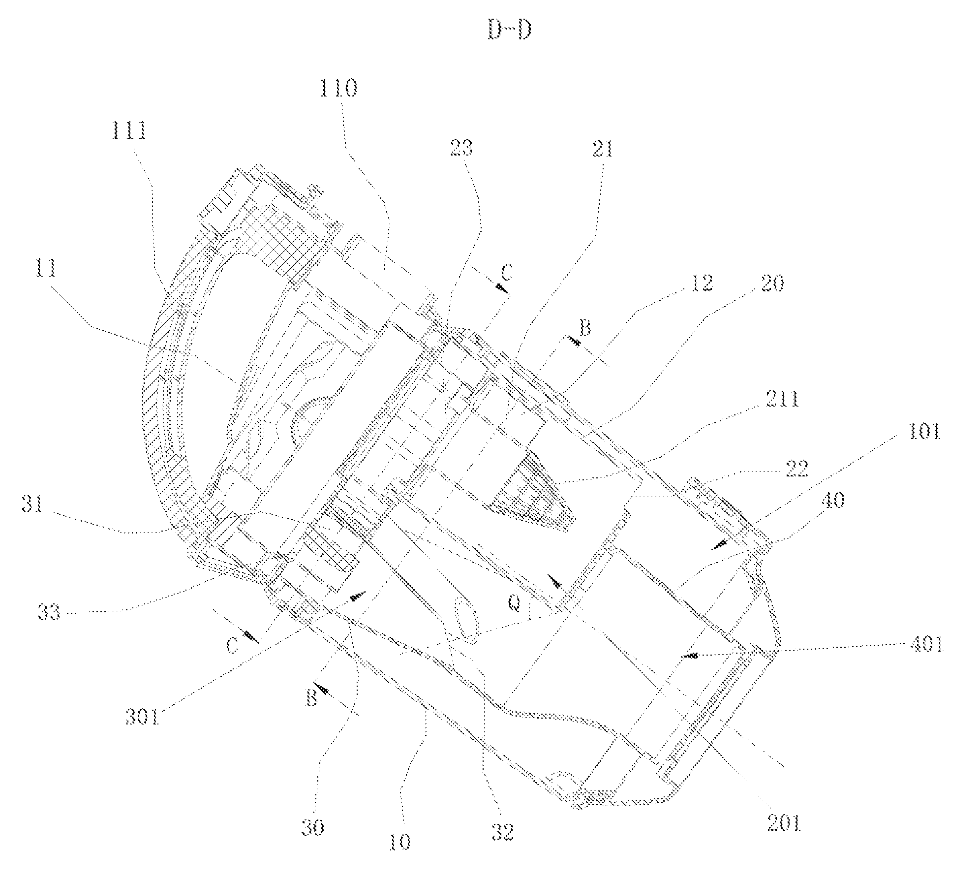
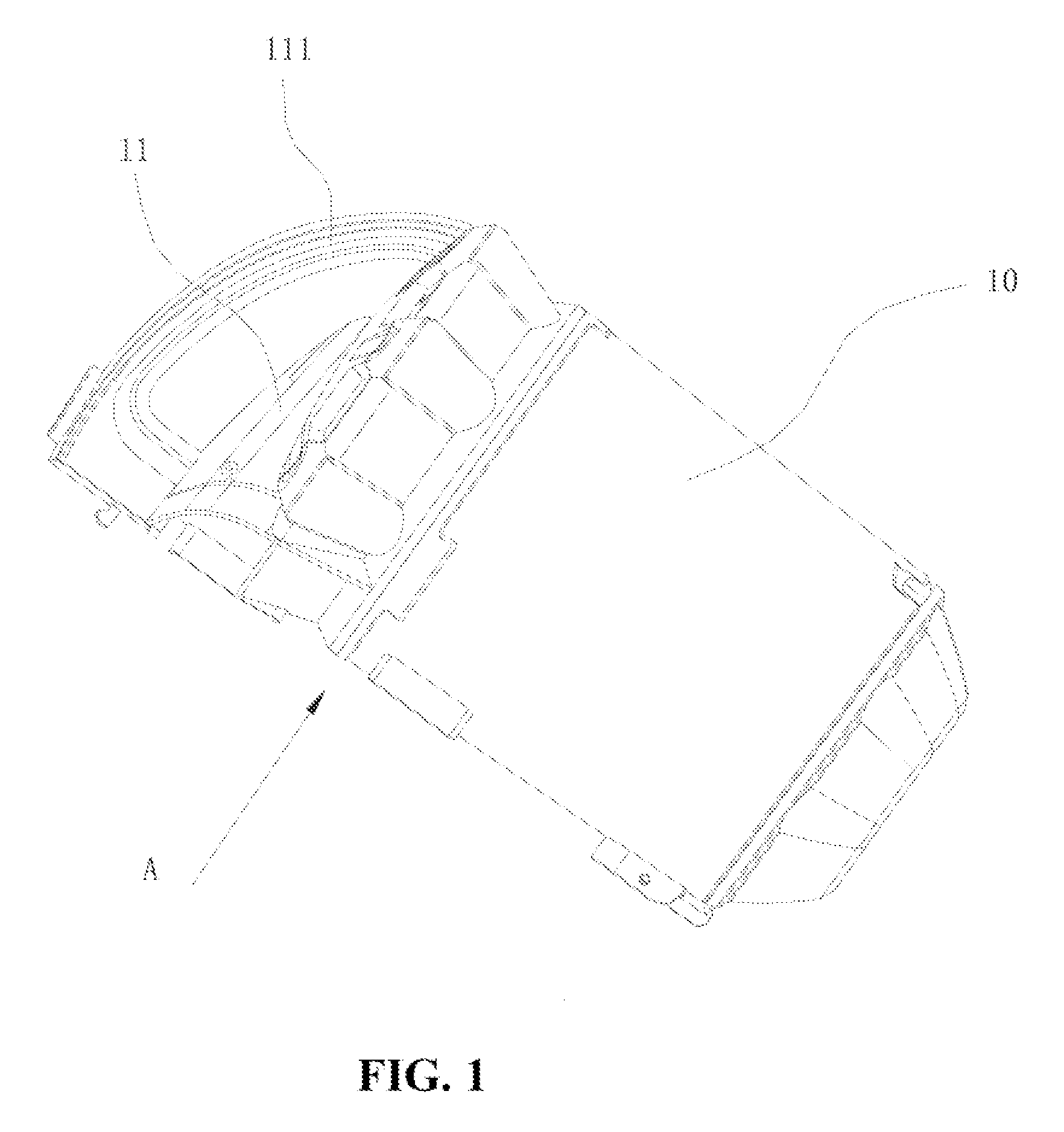
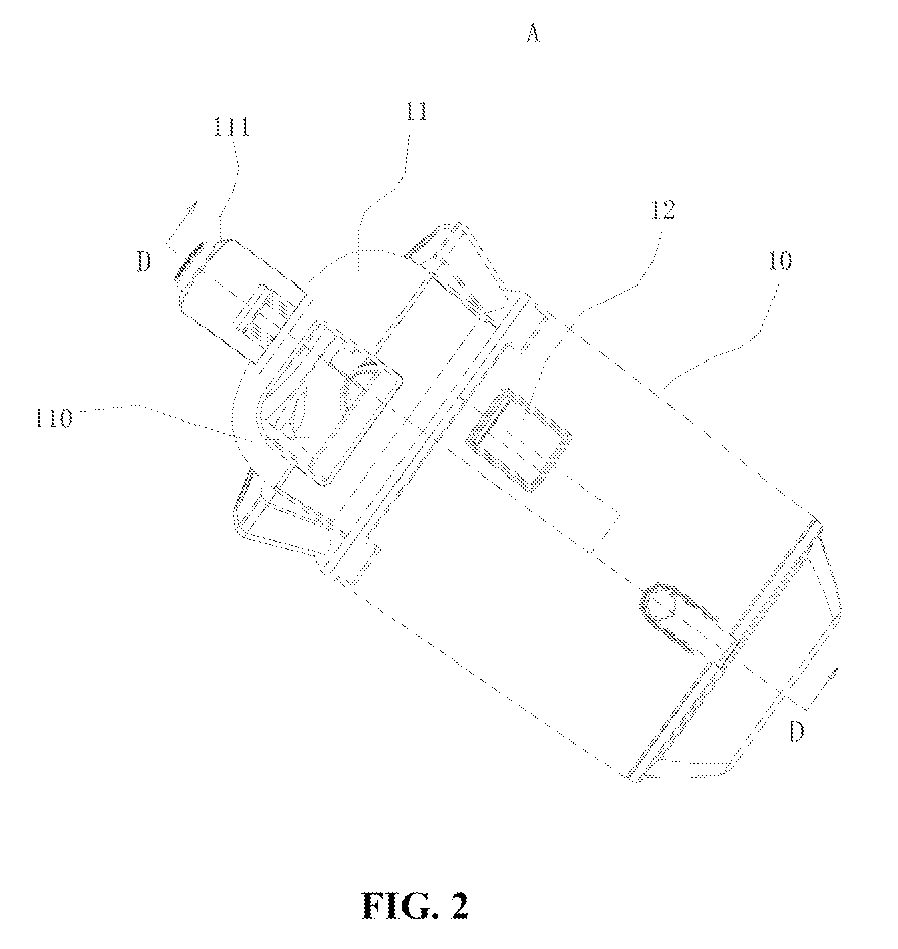
[0020]As shown in FIG. 1 and FIG. 2, the multi-cyclone separating apparatus comprises an outer barrel 10 having a gap. An air inlet passage 12 which would be introduced hereinafter is formed from the gap extending inward the outer barrel 10.

[0021]There is an upper cover 11 set on the outer barrel 10 and the upper cover 11 has a handle 111 convenient for taking, the upper cover 11 has an air outlet 110 to be connected with a negative pressure source of a vacuum cleaner utilizing the multi-cyclone separating apparatus according to the present invention.

[0022]As show in FIG. 3, it reflects the inner structure of the multi-cyclone separating apparatus. The multi-cyclone separating apparatus of vacuum cleaner comprising upstream cyclone 20 forming upstream separating chamber 201 inside, downstream cyclone 30 at least one of which forming downstream separating chamber 301 inside, upstream cyclone 20 is inside of the outer barrel 10. The upper part of upstream separating chamber 201 is con...


PUM

PropertyMeasurementUnit
angleaaaaaaaaaa
angleaaaaaaaaaa
angleaaaaaaaaaa

Abstract

A multi-cyclone separating apparatus of vacuum cleaner comprises a upstream cyclone forming upstream separating chamber inside, downstream cyclones at least one of which forming downstream separating chamber inside, the upper part of the upstream cyclone chamber is connected with an air inlet passage, said upstream cyclone has a upstream guide air intake inside, the downstream cyclone has a downstream air intake and the downstream cyclone has a downstream guide outlet inside, an air passage is formed between upstream guide air intake and downstream guide outlet which connected with the two. The multi-cyclone separating apparatus also comprises an outer cyclone body, the upstream cyclone is located inside of the outer cyclone body and the entrance of air inlet passage is located at the outer cyclone body or extend to the outside of the outer cyclone body.

Description

CROSS REFERENCE TO RELATED APPLICATIONS[0001]This application claims the benefit of People's Republic of China application Serial No. 2012205113981 filed on Sep. 29, 2012, under 35 USC Sec. 119(a) hereby specifically incorporated by reference in its entirely.FIELD OF THE INVENTION[0002]The invention relates to a dust collector of a vacuum cleaner, especially to a multi-cyclone separating apparatus.DESCRIPTION OF THE RELATED ART[0003]In prior art, a multi-cyclone separator for a vacuum cleaner comprises an upstream cyclone separator and a downstream cyclone separator or a plurality of downstream cyclone separators surrounding the upstream cyclone separator. A primary dust chamber is formed under the upstream cyclone separator for collecting big dust separated by the upstream cyclone separator. A secondary dust chamber is formed under the downstream cyclone separator for collecting the small dust separated by the downstream cyclone separator. The secondary dust chamber is outside and ...

Claims


Application Information

Patent Timeline
Patent Type & Authority Patents(United States)
IPC IPC(8): B01D45/12A47L9/16
CPCA47L9/1641A47L9/1625A47L9/1666A47L9/1683A47L9/1691
Inventor CHEN, GUOZHANG
Owner YUYAO JINGCHENG HIGH & NEW TECH
Why Eureka
Try Eureka