Unlock instant, AI-driven research and patent intelligence for your innovation.

Optical lens for using in illumination system of imaging scanner

a technology of illumination system and optical lens, applied in the direction of instruments, sensing record carriers, sensing by electromagnetic radiation, etc., can solve the problems of sacrificing scanner performance, causing users big discomfort, and consuming more power

Active Publication Date: 2016-11-29
SYMBOL TECH LLC
View PDF18 Cites 3 Cited by
  • Summary
  • Abstract
  • Description
  • Claims
  • Application Information

AI Technical Summary

Benefits of technology

The solution significantly improves eye comfort by making the apparent light source larger, achieving 25 times better perception compared to traditional designs, while maintaining high power efficiency and illumination pattern quality.

Problems solved by technology

The bright illumination has been causing big discomfort to users.
Unfortunately this is achieved with the sacrifice of the scanner performance and the higher power consumption due to the power loss from the nature of light diffuser.
It is often very challenging if not impossible to meet the performance requirement and in the meantime to provide acceptable eye comfort.

Method used


Image

  • Optical lens for using in illumination system of imaging scanner
  • Optical lens for using in illumination system of imaging scanner
  • Optical lens for using in illumination system of imaging scanner

Examples


Embodiment Construction

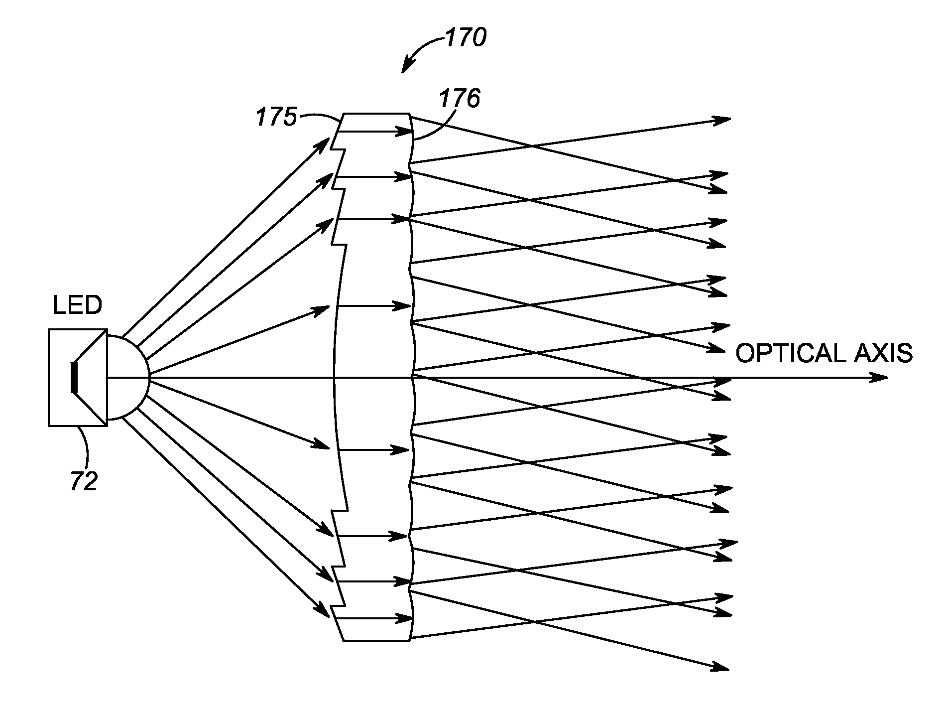
[0013]An imaging scanner includes an illumination light source, an illumination lens, an imaging lens arrangement, an imaging sensor, and a controller. The illumination lens includes a first Fresnel surface facing the illumination light source and a second surface having a microlens array thereon. The first Fresnel surface is configured to direct light received from the illumination light source towards the second surface to generate illumination light towards a target object through the microlens array on the second surface. The illumination light has a predetermined illumination field of view. The imaging sensor has photosensitive elements configured to detect light from the target object within an imaging field of view through the imaging lens arrangement at least during a time period when the target object is illuminated by the illumination light. The imaging sensor is configured to output image data from the photosensitive elements. The controller is configured for processing t...


PUM


Abstract

An imaging scanner includes an illumination light source and a hybrid illumination lens. The hybrid illumination lens includes a first Fresnel surface facing the illumination light source and a second surface having a microlens array thereon. The first Fresnel surface is configured to direct light received from the illumination light source towards the second surface to generate illumination light towards a target object through the microlens array on the second surface.

Description

BACKGROUND[0001]Various electro-optical systems have been developed for reading optical indicia, such as barcodes. A barcode is a coded pattern of graphical indicia comprised of a series of bars and spaces of varying widths. In a barcode, the bars and spaces have differing light reflecting characteristics. Some of the barcodes have a one-dimensional structure in which bars and spaces are spaced apart in one direction to form a row of patterns. Examples of one-dimensional barcodes include Uniform Product Code (UPC), which is typically used in retail store sales. Some of the barcodes have a two-dimensional structure in which multiple rows of bar and space patterns are vertically stacked to form a single barcode. Examples of two-dimensional barcodes include Code 49 and PDF417.[0002]Systems that use one or more imaging sensors for reading and decoding barcodes are typically referred to as imaging-based barcode readers, imaging scanners, or imaging readers. An imaging sensor generally in...

Claims


Application Information

Patent Timeline
Patent Type & Authority Patents(United States)
IPC IPC(8): G06K7/10
CPCG06K7/10732G06K7/10722G06K7/10831G06K7/10544G06K7/10702
Inventor CHEN, CAIHUA
Owner SYMBOL TECH LLC