Pipe joint

a pipe joint and pipe connection technology, applied in the direction of hose connections, couplings, branching pipes, etc., can solve the problems of resistance, affecting and affecting the operation of the pipe, so as to improve the sealing characteristics of the pipe joint and enhance the operability

Active Publication Date: 2017-01-31
SMC CORP
View PDF30 Cites 56 Cited by
  • Summary
  • Abstract
  • Description
  • Claims
  • Application Information

AI Technical Summary

Benefits of technology

[0006]A general object of the present invention is to provide a pipe joint, which enhances operability when a tube is both installed and separated from a body portion, and in which sealing characteristics of the pipe joint are improved.

Problems solved by technology

As a result thereof, when the supply of fluid is halted and the flow passage pipe is taken out from the coupling main body portion, cases are known to occur in which separation of the flow passage pipe is difficult due to the latching pawls biting excessively into the flow passage pipe.
However, in this case, since there is no space into which the contact portion with the flow passage pipe can move, deformation of the contact portion is obstructed, and as a result, resistance occurs when the flow passage pipe is inserted.
Furthermore, in a situation where the flow passage pipe is installed with respect to the coupling main body portion, as a result of the sealing member being pressed upon and displaced by the fluid that flows through the interior of the coupling main body, the contact area of the sealing member with respect to the outer circumferential surface of the flow passage pipe is reduced, and there is a concern that the sealing characteristics of the sealing member may be deteriorated.

Method used


Image

  • Pipe joint
  • Pipe joint
  • Pipe joint

Examples


first embodiment

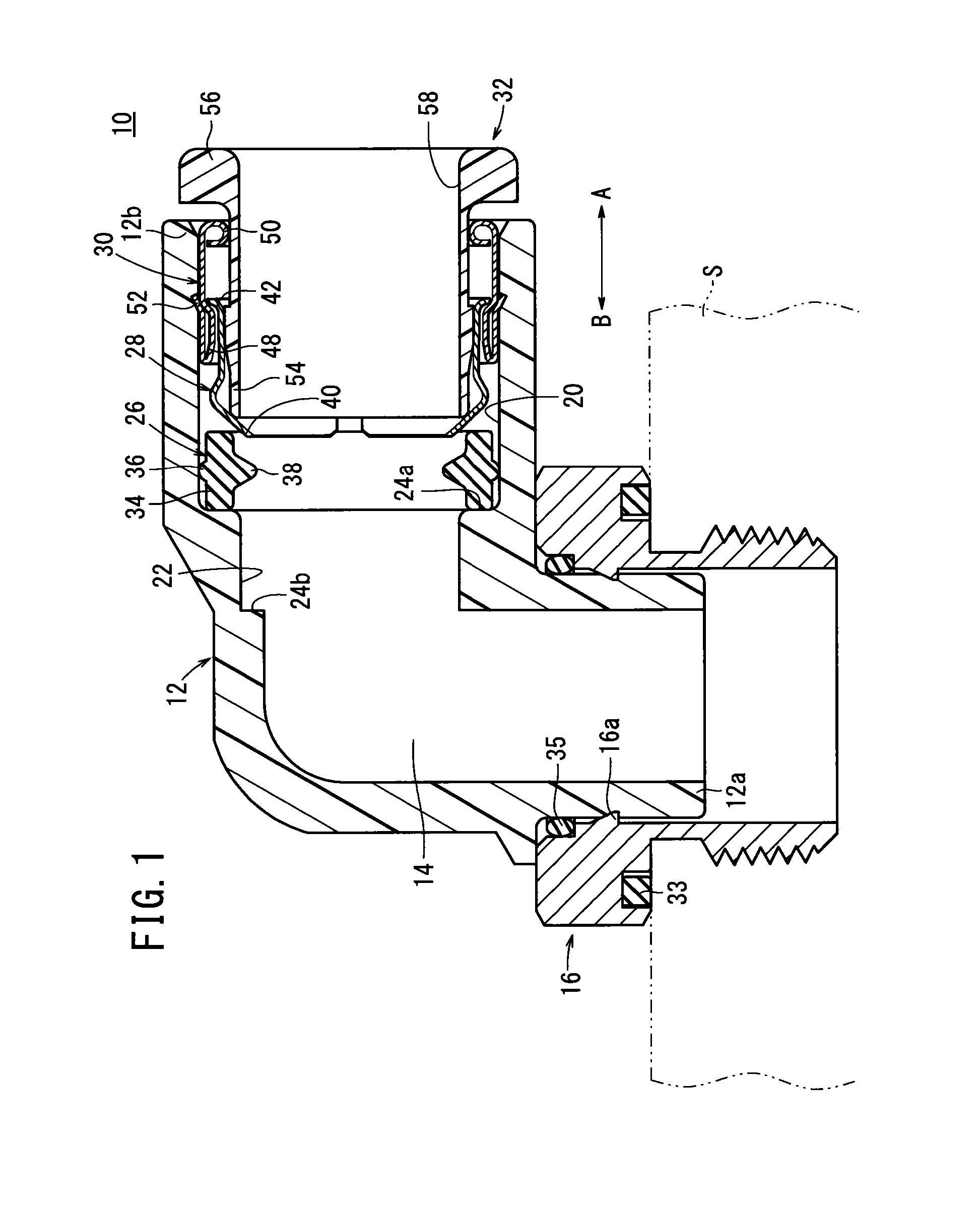
[0018]In FIG. 1, reference number 10 indicates a pipe joint according to the present invention.

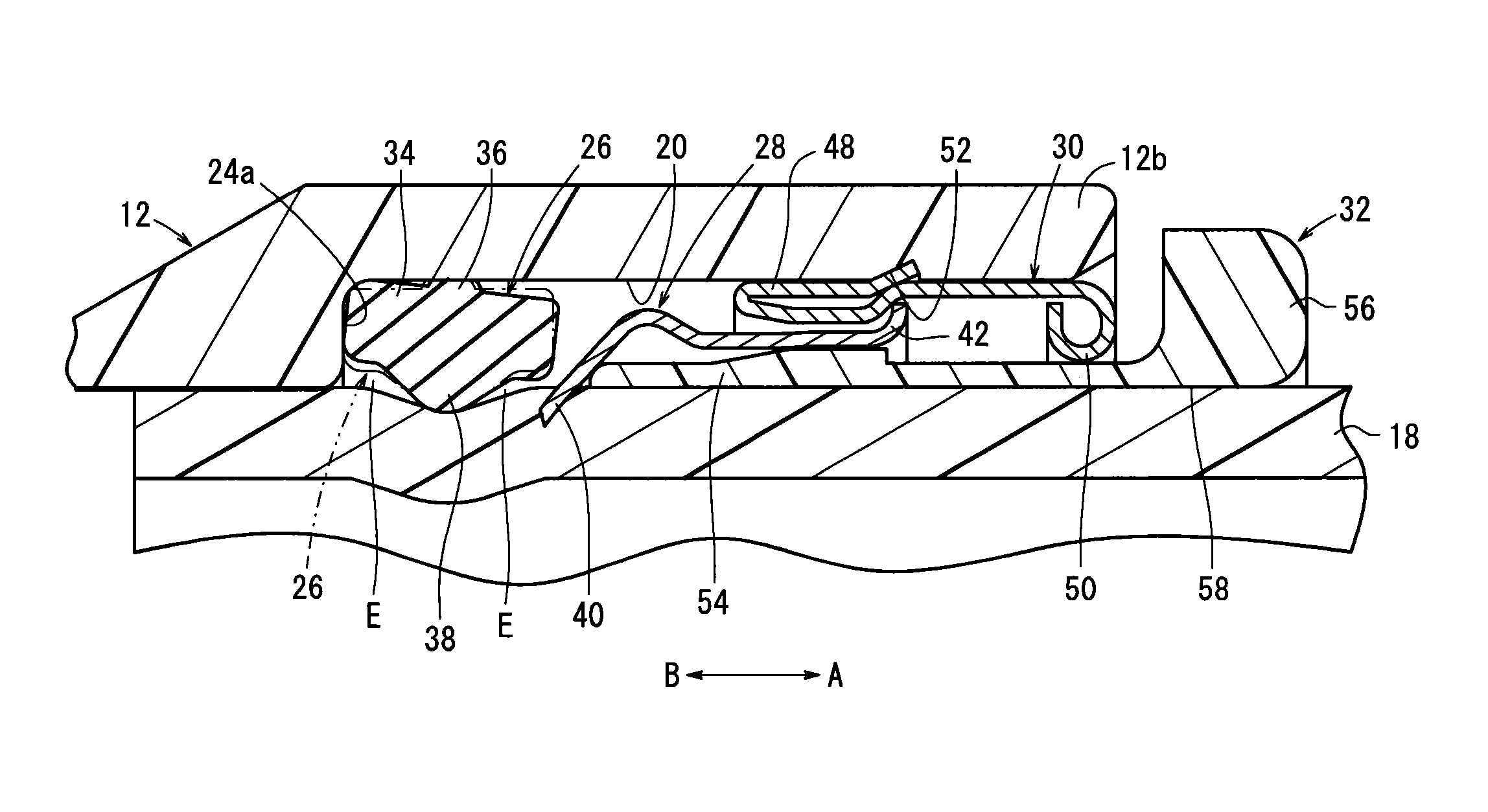
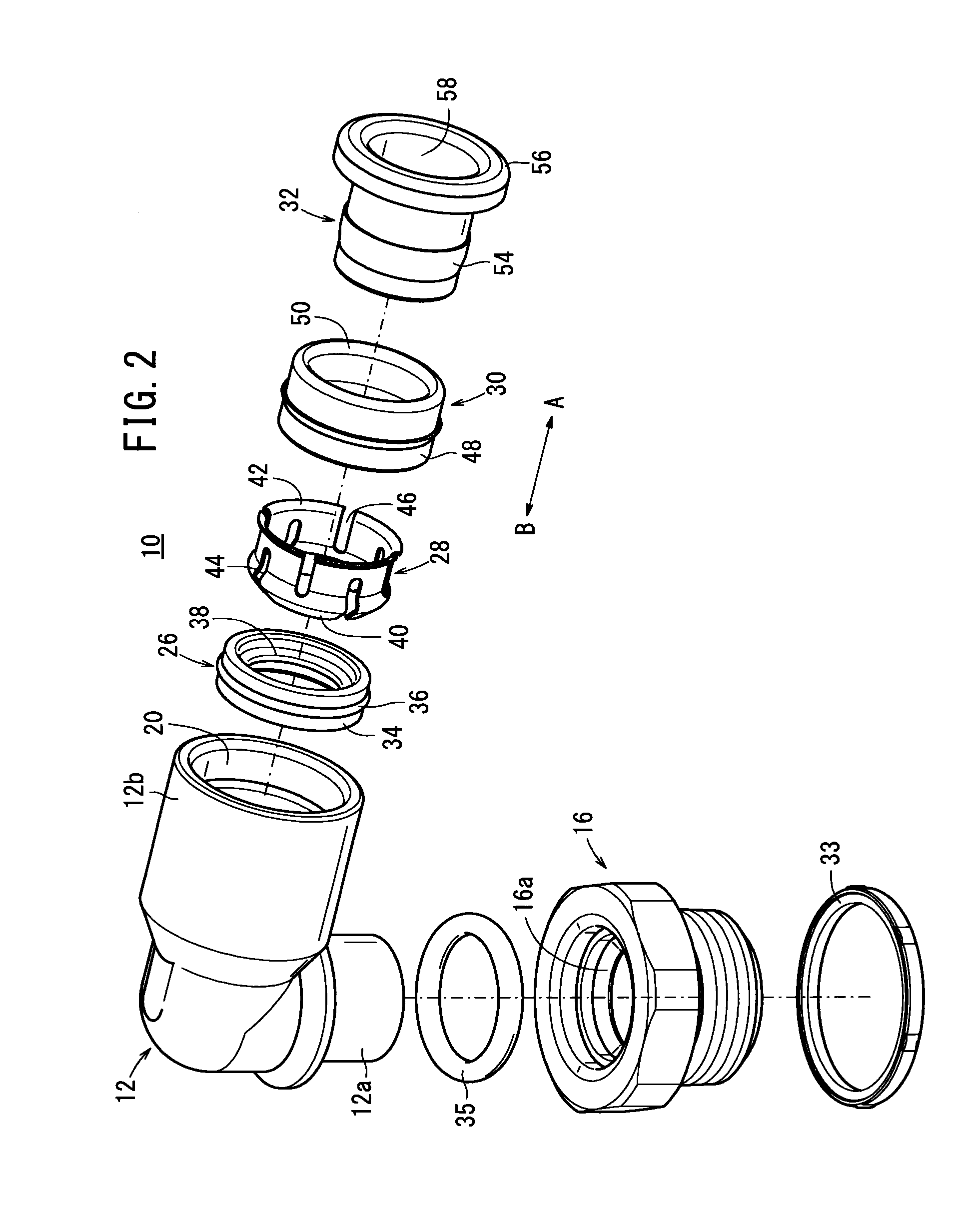
[0019]As shown in FIGS. 1 through 4, the pipe joint 10 is equipped with a tubular shaped body 12, formed from a resin material, which is bent substantially in an L-shape. A fluid passage 14 through which a fluid flows along the body 12 is formed in the interior of the body 12. Additionally, the fluid passage 14 opens at one end 12a and at another end 12b of the body and communicates with the exterior.

[0020]An adapter 16 is fitted onto one end 12a of the body 12 for facilitating attachment of the pipe joint 10 to another apparatus S. Conversely, on the other end 12b of the body 12, an opening 20 is formed, into which a fluid tube (tube) 18 is inserted, together with a connection passage 22 that connects the opening 20 with the fluid passage 14. The aforementioned body 12 is not limited to the case of being formed from a resin material, and may be formed from a metallic material, for example...

second embodiment

[0069]With the second embodiment constructed as described above, in a pipe joint 100, which includes the body 102 formed from a metallic material and which extends in a straight line fashion along the axial direction (the direction of arrows A and B), by use of the packing 26 comprising the main body portion 34, the sealing member 38 that projects in a triangular shape with respect to the main body portion 34 toward the inner circumferential side, and the bulging portion 36 that bulges outwardly from the main body portion 34, when the fluid tube 18 is inserted into the body 102, since compared to the packing used in the conventional pipe joint, the contact area between the sealing member 38 and the fluid tube 18 is reduced, resistance upon insertion of the fluid tube 18 while in sliding contact with the sealing member 38 is lessened. Together therewith, since accompanying such a reduction in contact area, the pressing force from the sealing member 38 with respect to the outer periph...


PUM


Abstract

A pipe joint has a body, and an annular packing is mounted to the opening of the body into which a fluid tube is inserted. The packing is provided with: a body section having a substantially rectangular cross-sectional shape; and a seal section protruding in the radial direction from the inner peripheral surface of the body section. The seal section is formed at substantially the center of the body section in the widthwise direction thereof and is formed in a triangular cross-sectional shape tapering to the inner peripheral side. When the fluid tube is inserted in the opening, the seal section of the packing makes sliding contact with the outer peripheral surface of the fluid tube.

Description

TECHNICAL FIELD[0001]The present invention relates to a pipe joint to which tubes that serve as an inlet and an outlet for a fluid, for example, are connected.BACKGROUND ART[0002]Heretofore, a pipe joint has been used for connecting fluid tubes to a fluid pressure device such as a cylinder. Such a pipe joint, for example as disclosed in Japanese Laid-Open Patent Publication No. 03-140697, is equipped with a cylindrical shaped coupling main body portion. In the interior of the coupling main body portion, a ring shaped sealing member is installed, and adjacent to the sealing member, latching pawls are provided, for engagement with a flow passage pipe, which is inserted into the interior of the coupling main body portion. In addition, when the flow passage pipe is inserted from one end side of the coupling main body portion, the sealing member, which has a rectangular shape in cross section, abuts against the outer peripheral surface of the flow passage pipe, so that leakage of the flu...

Claims


Application Information

Patent Timeline
Patent Type & Authority Patents(United States)
IPC IPC(8): F16L37/091F16L41/00
CPCF16L37/0915F16L41/007F16L19/02F16L21/08F16L37/12
Inventor FURUYA, MASAYOSHITAKANASHI, AKIHITO
Owner SMC CORP
Why Eureka
Try Eureka