Rotation shaft device

a technology of rotating shaft and rotating shaft, which is applied in the direction of wing accessories, instruments, manufacturing tools, etc., can solve the problems of inability to provide a timely positioning function, the flat and adjacent arrangement effect of the supporter may be affected, and the table computer cannot provide a stably positioning effect while being in the standing position at various angles, etc., to achieve simple assembly, reduce the effect of components

Active Publication Date: 2018-01-30
JARLLYTEC CO LTD
View PDF15 Cites 10 Cited by
  • Summary
  • Abstract
  • Description
  • Claims
  • Application Information

AI Technical Summary

Benefits of technology

[0008]One primary objective of the present invention is to provide a rotation shaft device, which has less components and has the internal structural space being effectively utilized for achieving advantages of thin in thickness and simple in assembly, so that the rotation shaft device would not increase the whole thickness of a flat electronic device, for example a tablet computer or an all-in-one (AIO) computer while the structural strength of the rotation shaft device can be kept.

Problems solved by technology

However, when a user touches for operating the flat electronic device, for example a tablet computer, the tablet computer shall not only be horizontally placed but also the tablet computer should be provided with a function of adjusting the standing angle in a stage-less or multi-stage means, but the above-mentioned rotation shaft device can only be used for supporting the tablet computer without the stage-less or multi-stage adjusting and positioning effect, so that the tablet computer is unable to be provided with a stably positioning effect while being in the standing status at various angles.
In addition, the core shaft of the rotation shaft device and the rotation center line of the supporter are coaxially arranged, so that the pivoting portion of the tablet computer may be relatively protruded and not easily be shield by the supporter, when the supporter is folded to be adjacent to a wall surface of the tablet computer, a flatly and adjacently arranging effect of the supporter may be affected.
However, the above-mentioned friction structure can only provide a timely positioning function to the tablet computer and the supporter.

Method used


Image

  • Rotation shaft device
  • Rotation shaft device
  • Rotation shaft device

Examples


Embodiment Construction

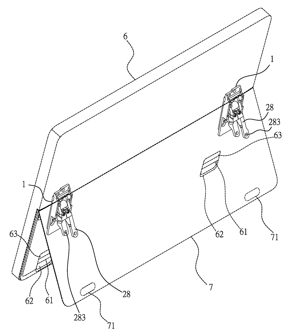
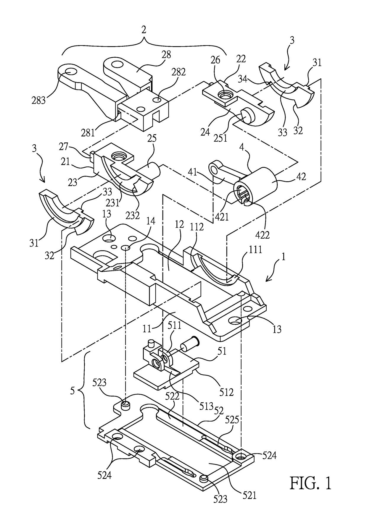
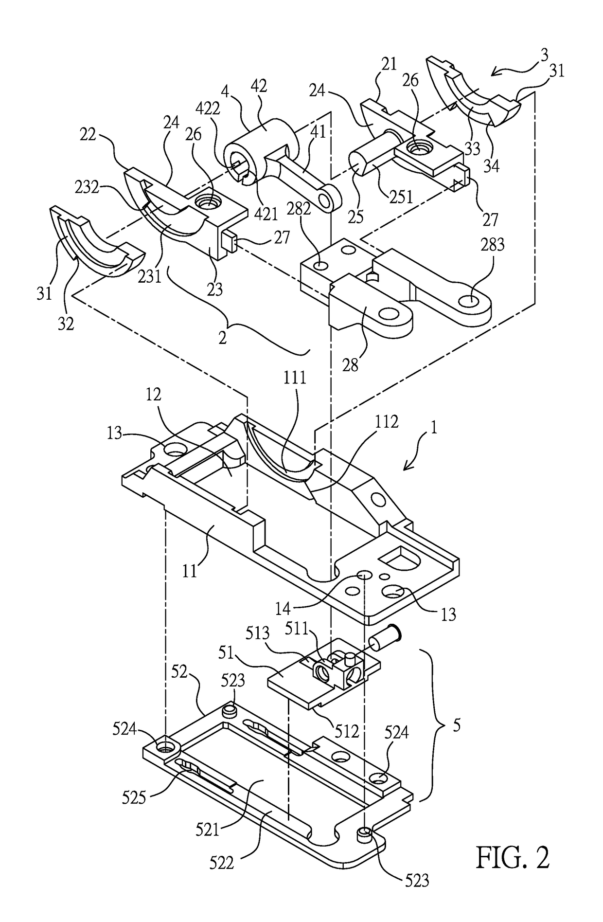
[0033]Referring from FIG. 1 to FIG. 6, the present invention provides a rotation shaft device, which comprises a base 1, a first rotation unit 2, a pair of second rotation units 3, a torsion unit 4 and a slide mechanism 5.

[0034]The base 1 is formed as a rectangular seat member, a hollow slot 12 is formed between a pair of lateral walls 11 thereof, and a space defined between the pair of lateral walls 11 is served to allow the first rotation unit 2 and the pair of second rotation units 3 to be accommodated and rotated therein. For allowing the first rotation unit 2 and the pair of second rotation units 3 to be smoothly rotated between the pair of lateral walls 11, adjacent surfaces of the pair of lateral walls 11 and the pair of second rotation units 3 are respectively formed with a first rotation guiding structure, for example a first arc-shaped guiding slot 111 and a first arc-shaped guiding rail 31, so that the pair of second rotation units 3 can be rotated along the pair of first...


PUM


Abstract

A rotation shaft device comprises: a base; a first rotation unit; a pair of second rotation units; a torsion unit, having a connection rod; a slide mechanism, including a slide block disposed in a hollow slot and having the top surface formed with a pivotal part, and a pair of slide pieces are disposed at two opposite sides of the slide bock; and a bottom seat, formed with an accommodation part, two opposite sides defined on a top surface of the accommodation part and/or a bottom surface of the base are formed with a pair of slide slots allowing the pair of slide pieces to be disposed; the slide block is pivotally connected to the torsion unit and the first rotation unit, thus the pair of slide pieces can stably slide between the bottom surface of the base and the pair of slide slots.

Description

BACKGROUND OF THE INVENTION1. Field of the Invention[0001]The present invention relates to a rotation shaft device, especially to a rotation shaft device disposed between a flat electronic device and a supporter.2. Description of Related Art[0002]A flat electronic device, for example a tablet computer or an all in one (MO) computer, is pivoted with a supporter for enabling the flat electronic device to be arranged in a standing status, and the supporter is connected with a rotation shaft device for achieving effects of rotating (for unfolding or folding) and supporting the tablet computer to be in the standing status. The rotation shaft device includes a core shaft and a friction disk disposed on the core shaft, at least one elastic disk or a spring, and an anti-loosening nut.[0003]Wherein, the main component for achieving the rotation effect is the core shaft, one end of the core shaft is pivoted with the supporter located in a rotation center line, and the other end of the core sh...

Claims


Application Information

Patent Timeline
Patent Type & Authority Patents(United States)
IPC IPC(8): F16C11/04E05D11/00E05D7/00E05D3/12
CPCF16C11/04E05D3/12E05D11/00E05D7/00E05Y2900/606Y10T16/5406G06F1/1681E05D11/082
Inventor HSU, YU-TSUNKAO, WEI-CHEN
Owner JARLLYTEC CO LTD
Why Eureka
Try Eureka