
Ribbed plate support and inflation deployment type heavy caliber paraboloidal antenna
A parabolic, large-diameter technology, applied in the field of satellite communication antennas, can solve the problems of heavy launch weight, high manufacturing cost, and large launch volume, and achieve the effect of reducing launch cost, reducing launch weight, and small launch volume.
Patent Information
- Authority / Receiving Office
- CN · China
- Patent Type
- Patents(China)
- Current Assignee / Owner
- Publication Date
- 2008-08-13
- Estimated Expiration
- Not applicable · inactive patent
Smart Images
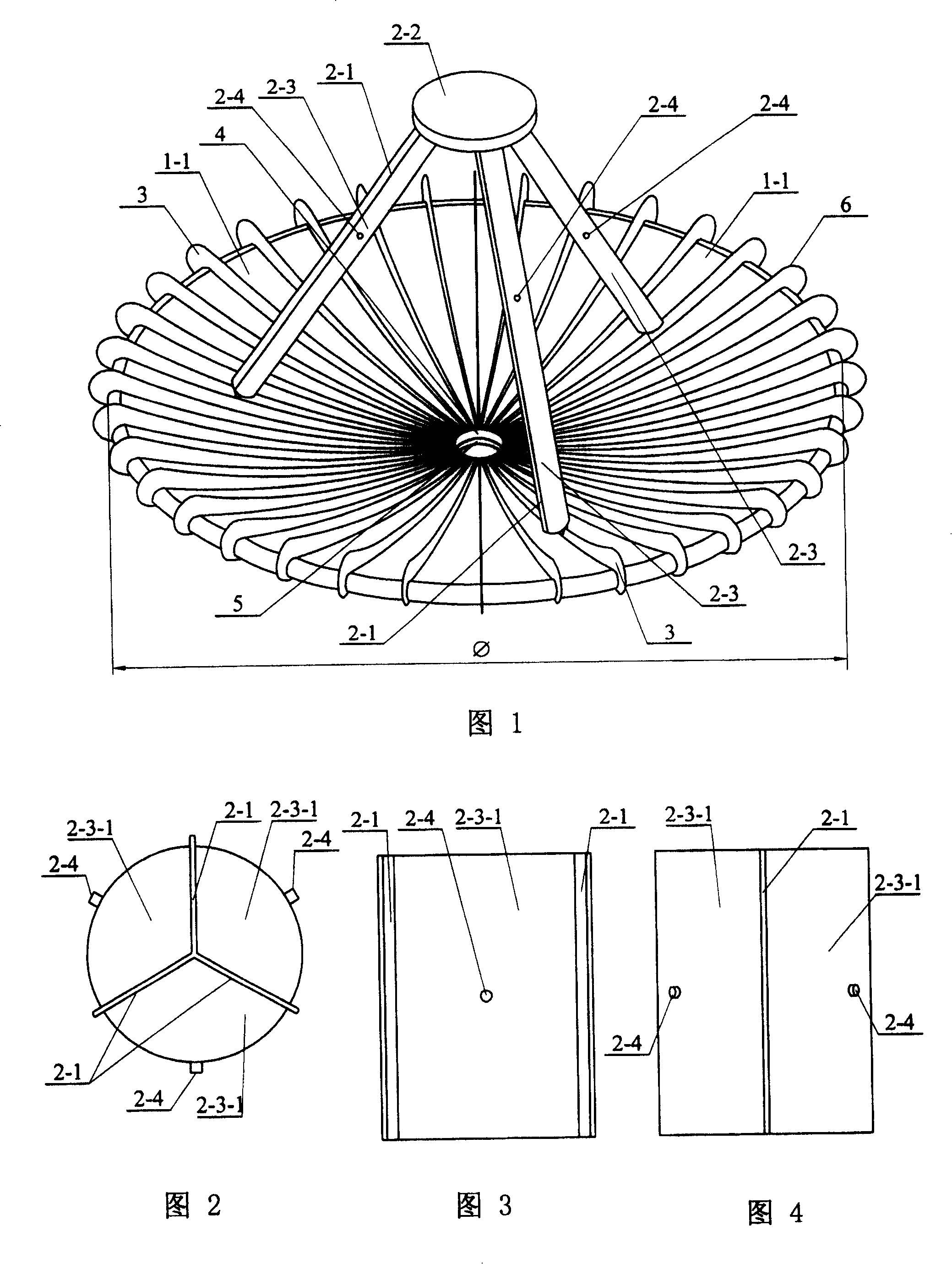
Figure 1 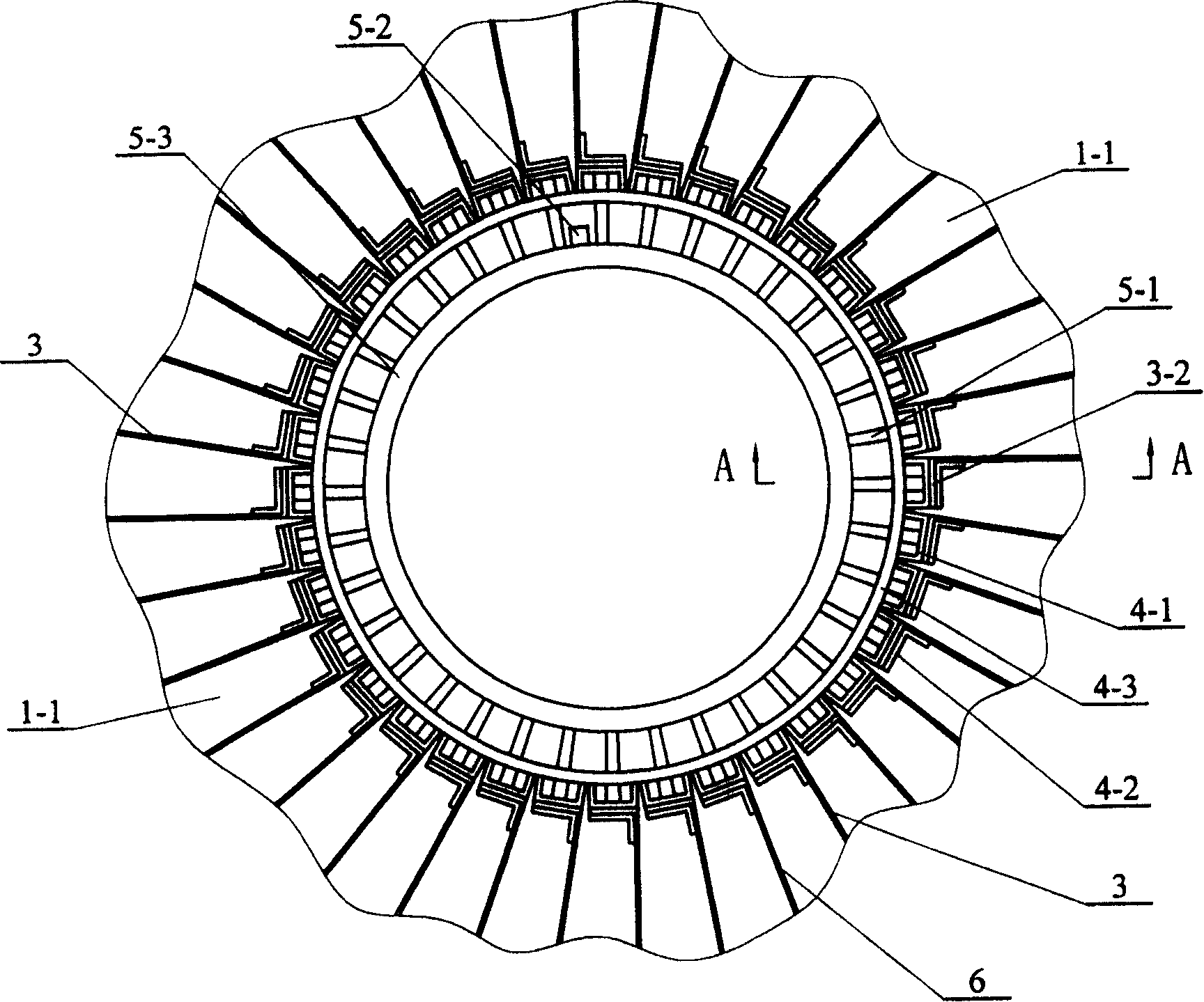
Figure 2 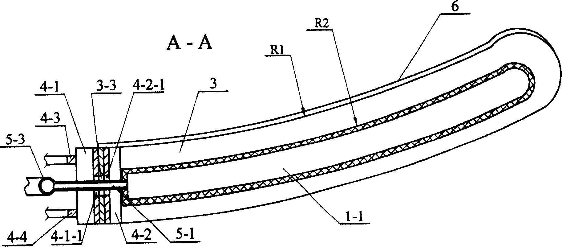
Figure 3
Abstract
Description
Technical field:
[0001] The invention relates to a satellite communication antenna for emitting and receiving electromagnetic waves, in particular to a large-diameter parabolic antenna supported by ribs and inflatable and expandable. Background technique:
[0002] Antenna is an important radio device for transmitting and receiving electromagnetic waves. Without antenna, there would be no radio communication. The communication antennas used on satellites are mostly linear antennas or small-diameter planar antennas due to the limitation of rocket launch volume and effective launch load. It has been proved by experiments that linear antennas or small-diameter planar antennas are not as good as large-diameter parabolic antennas in terms of focusing and collection capabilities, so large-diameter parabolic antennas are especially suitable for long-distance satellite communications. However, existing large-diameter parabolic antennas have hindered the application of large-diameter...
Examples
specific Embodiment approach 1
[0006] Specific Embodiment 1: This embodiment is described in conjunction with FIG. 1. This embodiment is composed of a parabolic reflector, a support frame assembly, a curved rib 3, a central connecting frame 4, an inflator 5, and a reflective surface layer 6; The reflector is composed of a group of fan-shaped unit air chambers 1-1 spaced apart along the radius of the parabola, and the ribs 3 are fixedly connected between two adjacent fan-shaped unit air chambers 1-1, and the ribs 3 The upper end surface is fixedly connected to the lower end surface of the partition plate 2-1 in the corresponding support frame assembly, and one end of each rib 3 close to the central connecting frame 4 is fixedly connected to the central connecting frame 4, and each rib 3 The reflective surface layer 6 is attached to the upper end surface, and one end of each fan-shaped unit air chamber 1-1 close to the inflator 5 is fixedly connected with the inflator 5, the support frame assembly is coaxial w...
specific Embodiment approach 2
[0007] Specific Embodiment Two: This embodiment is described in conjunction with FIG. 1. The reflector of this embodiment is composed of thirty-six fan-shaped unit air-filled chambers 1-1 spaced apart along the radius of the paraboloid, and two adjacent fan-shaped unit air-filled chambers 1-1 The sides of the ribs are fixedly connected with the two sides of the rib plate 3 by bonding and sewing. Thirty-six fan-shaped unit air chambers 1-1 spaced apart along the radius of the paraboloid are used, and two adjacent fan-shaped unit air chambers 1-1 are fixedly connected by ribs 3 to form a reflector, and the ribs 3 support the reflector to form a paraboloid The shape of the reflector is formed by inflating and expanding the air chamber 1-1 of each fan-shaped unit, so the reflector has the advantages of light weight and high folding efficiency. Other components and connections are the same as those in the first embodiment.
specific Embodiment approach 3
[0008] Specific embodiment three: This embodiment is described in conjunction with Fig. 1, Fig. 2, Fig. 3, and Fig. 4. The support frame assembly of this embodiment consists of a connecting seat 2-2, an inflatable support tube 2-3, and a partition plate 2. -1. Air intake nozzle 2-4; each support tube 2-3 is divided into three chambers 2-3-1 with equal volume by three partition plates 2-1, each chamber 2-3- The side wall of 1 is fixedly connected with an air inlet nozzle 2-4, the chamber 2-3-1 is bonded to the partition plate 2-1, and the intersections of the three partition plates 2-1 are connected to each other by sewing, The lower end surface of the connecting seat 2-2 is uniformly fixedly connected with three supporting pipes 2-3 along the circumferential direction, and the upper end surface of the partition plate 2-1 on each supporting pipe 2-3 is fixed to the lower end surface of the connecting seat 2-2. connection, three support tubes 2-3 are placed in a cone shape, and ...