
Gas turbine preevaporation combustion-chamber for combusting ethanol fuel
A technology of gas turbine and ethanol fuel, which is applied in the direction of combustion chamber, continuous combustion chamber, combustion method, etc., can solve the problem of low boiling point, volatile and high latent heat of evaporation of ethanol fuel, which is not fully applicable, gas turbine combustion chamber cannot be fully used, and pollution emission structure Strength and other issues, to achieve the effect of reducing carbon black smoke and NOx generation, simple nozzle form and structure, and low maintenance costs
Patent Information
- Authority / Receiving Office
- CN · China
- Patent Type
- Patents(China)
- Current Assignee / Owner
- Publication Date
- 2010-06-02
- Estimated Expiration
- Not applicable · inactive patent
Smart Images
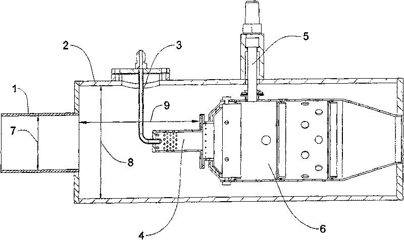
Figure 1 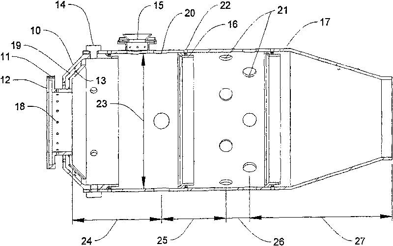
Figure 2 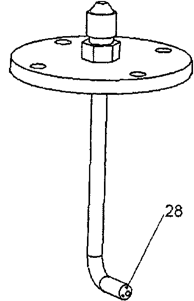
Figure 3
Abstract
Description
technical field
[0001] The invention relates to a gas turbine combustor, in particular to a gas turbine pre-evaporation combustor burning ethanol fuel. Background technique
[0002] Due to the limited supply of global fossil fuel reserves and the pressure of environmental pollution, the application of biomass fuels such as ethanol and biodiesel has been strongly advocated. Among them, ethanol is a renewable energy, which can be produced by fermenting sugar and other processes, thereby reducing the dependence on non-renewable fossil fuels and benefiting the sustainable development of human beings. The application of ethanol fuel has certain strategic significance for the global response to the energy crisis. In addition, the use of biological enzyme technology and agricultural product fermentation technology can produce ethanol from various biological materials such as grain, sucrose, and fiber, which can adjust the contradiction between grain supply and demand to a large ex...
Examples
Embodiment Construction
[0031] The present invention will be described in detail below in conjunction with the accompanying drawings and specific embodiments.
[0032] A gas turbine pre-evaporation combustor using ethanol fuel described in this embodiment adopts a single-tube cylindrical combustor structure, and is composed of a combustor casing 2 and a flame tube 6; the air flow enters the combustor from the combustor inlet 1 , into the flame tube through the opening on the pre-evaporation tube 4 and the flame tube 6; the liquid ethanol fuel is sprayed into the pre-evaporation tube 4 through the direct injection hole 28 on the ethanol supply path 3, under the action of the primary flow and the secondary swirling flow , the liquid ethanol is evaporated and mixed with air, and the mixed combustible gas enters the flame tube 6 from the outlet of the pre-evaporator tube 4; the ignition of the ethanol combustion chamber is realized by the electric spark igniter 5, and the entire ethanol combustion process...