
Device for measuring push-pull force output by rotating hydraulic cylinder
A technology of rotary hydraulic cylinder and push-pull force, which is used in measuring devices, measuring rapid changes, instruments, etc., can solve the problems of inability to test the pressure-holding performance of hydraulic locks, and achieve the effect of simple and convenient loading and unloading, no friction and wear, and little interference.
Patent Information
- Authority / Receiving Office
- CN · China
- Patent Type
- Applications(China)
- Current Assignee / Owner
- Publication Date
- 2010-06-02
- Estimated Expiration
- Not applicable · inactive patent
Smart Images
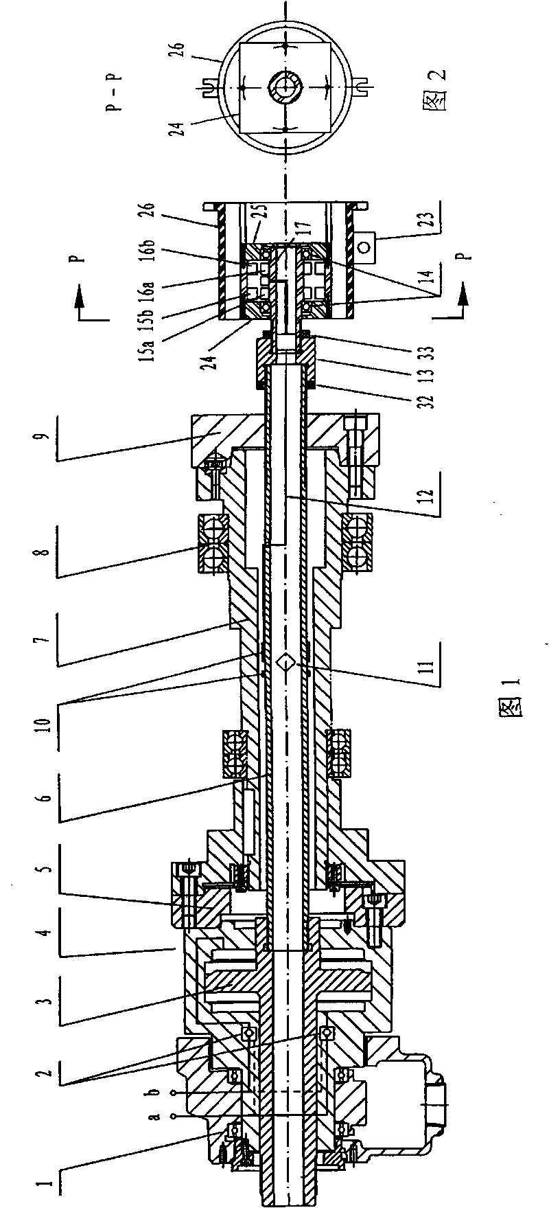
Figure 1 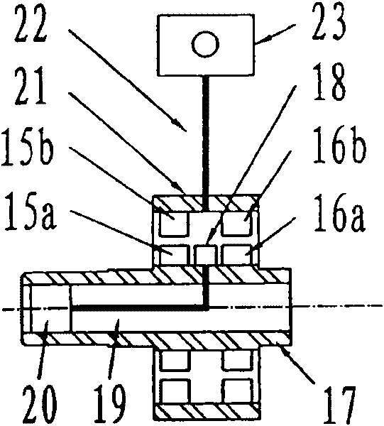
Figure 2 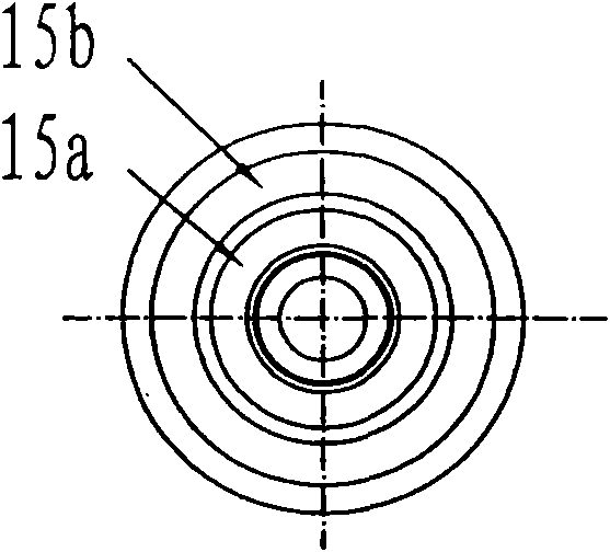
Figure 3
Abstract
Description
technical field
[0001] The invention relates to a force measuring device, in particular to a device for measuring the push-pull force output by a rotary hydraulic cylinder. Background technique
[0002] The rotary hydraulic cylinder is a functional part of the CNC lathe. It drives the power chuck to clamp and release the workpiece through the pull tube or pull rod. A hydraulic lock composed of two hydraulically controlled check valves is integrated inside the high-speed rotary hydraulic cylinder. When the high-speed rotary hydraulic cylinder suddenly encounters the oil supply pipeline burst, the hydraulic lock works to maintain the oil pressure in the high-pressure chamber of the rotary hydraulic cylinder. It remains unchanged to ensure that the rotary hydraulic cylinder still reliably drives the power chuck to clamp the workpiece, preventing the workpiece from flying out and causing safety accidents. The pressure holding capacity of the hydraulic lock is directly related t...
Examples
Embodiment Construction
[0025] The present invention will be further illustrated by the accompanying drawings and examples.
[0026] Such as figure 1 and figure 2 As shown, the present invention includes a rotor 17, a stator 21, a power supply and signal preprocessing circuit 18, two groups of rotary transformer couplers 15 and 16, a rotor terminal 20, and a junction box 23 equipped with AC-DC conversion and signal post-processing circuits. The two ends of the rotor 17 of the rotating strain signal coupler are respectively equipped with rolling bearings 14, and the two ends of the stator 21 are respectively equipped with square end covers 24 and 25, and the inner ring of the rolling bearing 14 is connected to the rotor 17. Ying fit, the outer ring of the rolling bearing 14 is a transition fit with the inner holes of the two square end caps 24 and 25 respectively, and the outer ring of the two square end caps 24 and 25 is fitted with the square on the through hole of the guide rail sleeve 26 as a ga...