
Fast wave eliminating/energy dissipating/cushioning device for mining
A buffer device and fast technology, applied in the direction of mining equipment, earthwork drilling, pillars/brackets, etc., can solve the problems of support equipment instability and damage, hydraulic buffer damage, high-speed deformation of rock mass, etc., to avoid mechanical production equipment Effect of damage, high compressive strength
Patent Information
- Authority / Receiving Office
- CN · China
- Patent Type
- Patents(China)
- Current Assignee / Owner
- Publication Date
- 2013-03-13
- Estimated Expiration
- Not applicable · inactive patent
Smart Images
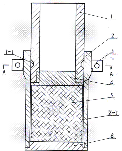
Figure 1 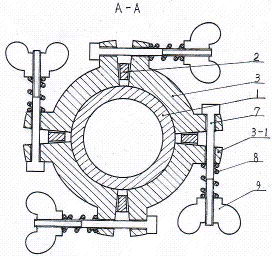
Figure 2 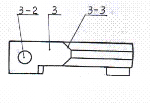
Figure 3
Abstract
Description
technical field
[0001] The invention belongs to mine safety supporting equipment, in particular to a mine-used rapid wave and energy consumption buffer device. Background technique
[0002] Rock burst is one of the main dynamic disasters in mining engineering. With the increasing mining depth of mineral resources, the occurrence frequency and damage degree of rock burst are becoming more and more intense. , roof fall and collapse, the overall instability of the support structure, the overturning and destruction of mechanical equipment, and even casualties and other accidents have seriously affected the safe mining of mineral resources and the safety of workers.
[0003] Commonly used mining support equipment includes wooden supports, steel supports, U-shaped steel supports, single hydraulic props and hydraulic supports, etc., all of which are mainly rigid supports. System security requirements. However, once there is a sudden rock burst in the mine, the elastic ground pres...
Examples
Embodiment Construction
[0015] Examples, see attached Figure 1~3 , the lower rigid sleeve 2 of the mine-used rapid wave dissipation and energy consumption buffer device is a cylinder with a thickened upper wall, the lower part is screwed to fix the external bottom cover 6, and the lower rigid sleeve 2 above the external bottom cover 6 is equipped with a cylinder Shaped plastic energy-absorbing material 5, leaving a gap 2-1 between the energy-absorbing material 5 and the inner wall of the lower rigid sleeve 2. An internal rigid bottom cover 4 is provided on the energy-absorbing material 5, and the internal rigid bottom cover 4 is screwed to fix the upper rigid sleeve 1. The upper rigid sleeve 1 overlaps with the upper thickening of the lower rigid sleeve 2. 1. A trapezoidal groove 1-1 is provided at the overlap between the outer wall and the inner wall of the lower rigid sleeve 2. At the trapezoidal groove 1-1 on the outer wall of the corresponding upper rigid sleeve 1, four pin clips 3 of the same ...