
Two-sided subminiature RFID (radio frequency identification) tag antenna
An RFID tag, tag antenna technology, applied in the direction of resonant antenna, antenna support/installation device, mid-position feed between antenna endpoints, etc., to achieve ultra-small size, wide operating bandwidth, omnidirectionality, and space reduction.
Patent Information
- Authority / Receiving Office
- CN · China
- Current Assignee / Owner
- Publication Date
- 2013-01-30
- Estimated Expiration
- Not applicable · inactive patent
Smart Images
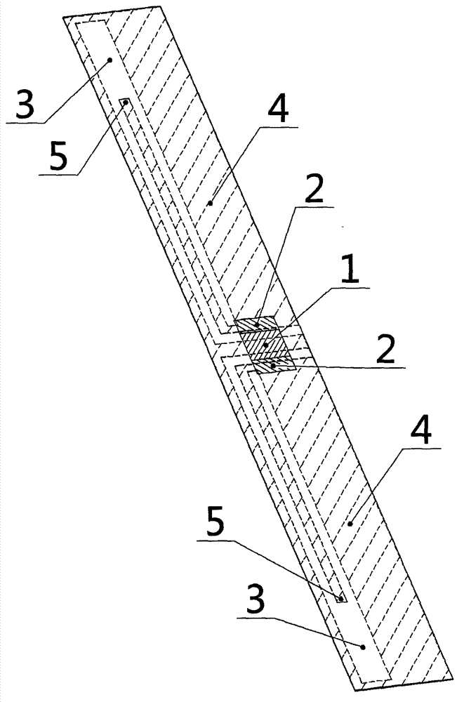
Figure 1 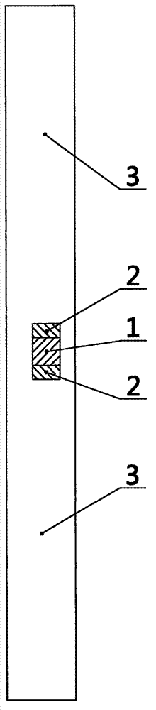
Figure 2 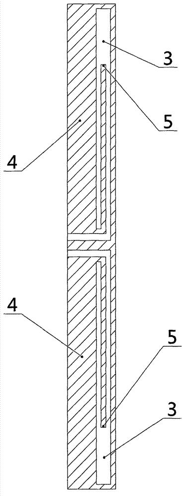
Figure 3
Abstract
Description
Technical field
[0001] The invention relates to a radio frequency identification electronic tag, especially an ultra-small, omnidirectional electronic tag. Background technique
[0002] Radio Frequency Identification (RFID) technology is a technology that uses wireless radio frequency to perform non-contact two-way data communication to identify targets. The radio frequency identification system usually consists of a reader and an electronic tag. The electronic tag is composed of a tag chip and a tag antenna. It exchanges data with the reader through electromagnetic waves and has functions such as intelligent reading and writing and encrypted communication. The tag antenna is a vital device in the RFID system. The RFID system transmits and receives electromagnetic waves through the tag antenna to realize the identification of the electronic tag by the reader.
[0003] Radio frequency identification systems mainly work in low frequency, high frequency, ultra high frequency and mic...
Examples
Embodiment Construction
[0025] The technical solution of the present invention will be further described below in conjunction with the drawings and specific embodiments of the specification.
[0026] It should be understood that the specific embodiments described herein are only used to explain the present invention, but not to limit the present invention.
[0027] Such as figure 1 Shown is a schematic structural diagram of a preferred embodiment of a double-sided ultra-small RFID tag antenna of the present invention. This embodiment includes a PET film substrate 3, an RFID tag chip 1 (Monza 4 chip is used in this embodiment, and the impedance at a working frequency of 915MHz is 11-j143Ω), a dipole-shaped structure 2, a symmetrical paperclip-shaped structure 4 According to different conditions and requirements, the dipole-shaped structure 2 and the symmetrical paperclip-shaped structure 4 can be processed with good conductors such as aluminum foil or silver.
[0028] Such as figure 2 Shown is a schematic ...