
Hydraulic automatic locking device of horizontal numerically controlled lathe tailstock
A CNC lathe and automatic locking technology, applied in turning equipment, tool holder accessories, tailstock/top and other directions, can solve the problems affecting the machining accuracy of parts, increase the labor intensity of workers, reduce production efficiency, etc., to improve production. Efficiency, compact structure, the effect of improving work efficiency
Patent Information
- Authority / Receiving Office
- CN · China
- Patent Type
- Applications(China)
- Current Assignee / Owner
- Publication Date
- 2013-03-27
- Estimated Expiration
- Not applicable · inactive patent
Smart Images
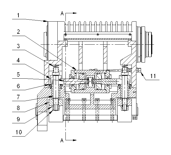
Figure 1 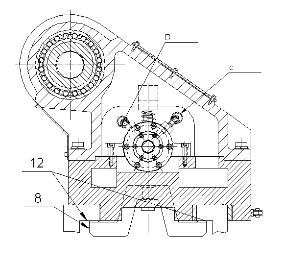
Figure 2
Abstract
Description
technical field
[0001] The invention relates to the technical field of auxiliary equipment for a horizontal numerically controlled lathe, in particular to a hydraulic automatic locking device for a tailstock of a horizontal numerically controlled lathe. Background technique
[0002] In the prior art, the tailstock of horizontal CNC lathes is manually locked, that is, the tailstock is locked by tightening the screws on the pressure plate. Although such a locking structure is simple, the locking is unreliable, which increases the labor force of the workers. Labor intensity reduces production efficiency. At the same time, if the tailstock needs to be locked again after moving, the concentric deviation between the tailstock and the machine tool spindle will affect the processing accuracy of the parts due to the difference in locking force. Contents of the invention
[0003] The purpose of the present invention is to overcome the above-mentioned defects in the prior art, provid...
Examples
Embodiment Construction
[0018] The structure of the present invention will be described below in conjunction with the accompanying drawings.
[0019] Such as figure 1 and figure 2 As shown, the hydraulic locking device of the tailstock of the horizontal CNC lathe of the present invention comprises a tailstock body 1, and a double piston rod oil cylinder 2 is installed in the lower space of the tailstock body 1, and the oil chamber in the piston rod oil cylinder 2 It is connected to the hydraulic control system of the machine tool through hydraulic oil pipes (11 in the figure is a straight-through joint). The double-piston rod cylinder 2 is equipped with two left and right piston rods 5, and the left and right piston rods 5 can respectively push the wedge 4 on the corresponding side under the hydraulic pressure of the cylinder to drive the pull rod 7 installed on the wedge 4 upward. Movement; the lower end of the pull rod 7 is equipped with a pressure plate 8, and the top is equipped with a compres...