
Scroll vacuum pump with magnetic fluid translational sliding thrust bearing and sealing structure
A technology of sliding thrust bearing and sealing structure, which is applied to parts of pumping devices for elastic fluid, pump parts of rotary piston type/oscillating piston type, rotary piston type pumps, etc., and can solve the problem that vacuum pumps cannot meet the sealing requirements And other issues
Patent Information
- Authority / Receiving Office
- CN · China
- Patent Type
- Patents(China)
- Current Assignee / Owner
- Publication Date
- 2016-12-28
Smart Images
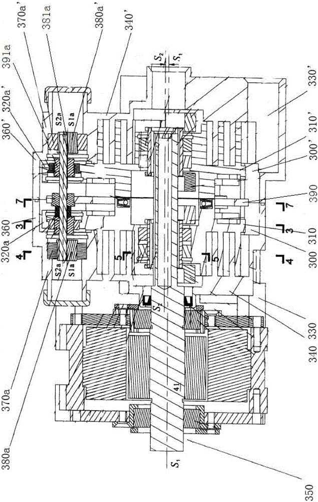
Figure 1 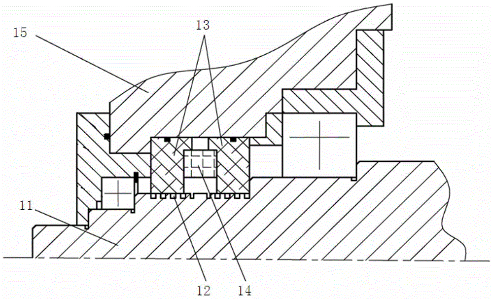
Figure 2 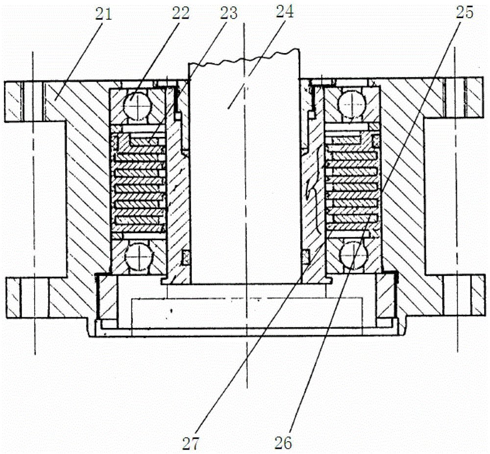
Figure 3
Abstract
Description
Technical field
[0001] The invention relates to the technical field of vacuum pumps, in particular to the technical field of a scroll vacuum pump with a magnetic fluid translational sliding thrust bearing and a sealing structure. Background technique
[0002] At present, magnetic fluid sealing technology has been used for gas isolation in axial rotation, and used in vacuum pumps to replace traditional mechanical seals; magnetic fluid sealing technology is developed on the basis of magnetic fluid. When the magnetic fluid is injected into the gap of the magnetic field, it can fill the entire gap to form a "liquid O-ring seal". The function of the magnetic fluid sealing device is to transmit the rotating motion to the sealed container, but to seal the gap between the rotating shaft and the bearing, and is often used for vacuum sealing. figure 1 For a schematic diagram of a magnetic fluid sealing device, please refer to figure 1 Shown. It includes a shaft 11 and a housing 15 located...
Examples
Embodiment approach
[0042] In further embodiments of the present invention, please refer to Figure 4 to Figure 7 Shown. The end surface of the magnet 72 close to the magnetic fluid is coated with a layer of anaerobic fluid coating 73. The material of the anaerobic fluid coating 73 is mainly polytetrafluoroethylene. The magnetic fluid coating 73 is used to converge The role of the magnetic fluid, thereby improving the pressure resistance and air tightness, and reducing the resistance, reducing the loss of the magnetic fluid.
[0043] In a further embodiment of the present invention, Figure 8 for Figure 5 The first scheme schematic diagram of the groove on the radial end face of the middle piston rear seat, please refer to Figure 8 Shown. The cross-sectional shape of the convex ring 92 provided between the two adjacent first annular grooves 91 on the radial end surface of the piston rear support 9 is rectangular.
[0044] In a further embodiment of the present invention, Picture 9 for Figure 5 Th...