
Welding fixture for precise stainless steel products
A welding tooling and stainless steel technology, applied in welding equipment, welding accessories, manufacturing tools, etc., can solve the problems of wrong edge at the joint of two joints, unqualified product size accuracy, etc., to reduce production costs, economical and Timeliness, the effect of improving the economic benefits of products
Patent Information
- Authority / Receiving Office
- CN · China
- Patent Type
- Applications(China)
- Current Assignee / Owner
- Publication Date
- 2015-12-16
- Estimated Expiration
- Not applicable · inactive patent
Smart Images
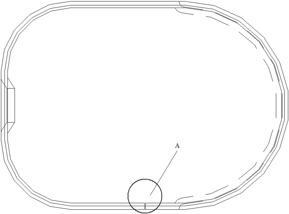
Figure 1 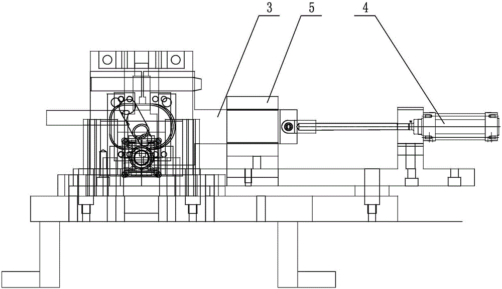
Figure 2 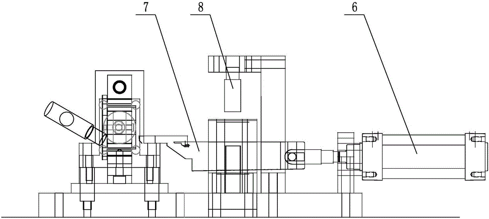
Figure 3
Abstract
Description
technical field
[0001] The invention relates to a welding tool for precision stainless steel products, in particular to a welding tool for ring-shaped precision stainless steel products, and belongs to the technical field of mechanical processing tools. Background technique
[0002] Such as figure 1 As shown, it is an existing stainless steel precision product, which needs to be figure 1 In the treatment of A, the tungsten argon arc welding without adding wire is implemented, and the two joints are welded together, and the precision of the joint after welding is required to reach 0.01mm. At present, after welding with simple tooling, it is found that the dimensional accuracy of the product is not up to standard, and there is a defect of wrong side at the connection of the two joints. Contents of the invention
[0003] The purpose of the present invention is to overcome the deficiencies in the prior art, provide a welding tool for precision stainless steel products, preci...
Examples
Embodiment Construction
[0011] The present invention will be further described below in conjunction with specific drawings.
[0012] Such as Figure 2 ~ Figure 4 As shown: the welding tooling for precision stainless steel products includes a bottom plate 1, a fixed block 2, a moving block 3, a first cylinder 4, a guide slide seat 5, a second cylinder 6, a limit block 7, and a cylinder seat 8.
[0013] Such as Figure 2 ~ Figure 4 As shown, the present invention includes a base plate 1, a fixed block 2 and a moving block 3 are installed on the base plate 1, between the fixed block 2 and the moving block 3, a workpiece is placed, and a welding torch is placed above the workpiece; the moving block 3 and the first cylinder The piston rod of 4 is connected, when the piston rod of the first cylinder 4 stretches out and retracts, it drives the moving block 3 to move, and the moving block 3 and the fixed block 2 press the workpiece to determine the position in the X direction; the moving block 3 is set On ...