
Injection locked frequency divider based on Lange coupler feedback structure
An injection locking and coupler technology, applied in the direction of automatic power control, electrical components, etc., can solve the problems of reduced locking range, reduced locking range, power loss, etc.
Patent Information
- Authority / Receiving Office
- CN · China
- Current Assignee / Owner
- Publication Date
- 2016-04-20
- Estimated Expiration
- Not applicable · inactive patent
Smart Images
Figure 1 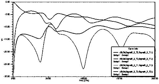
Figure 2 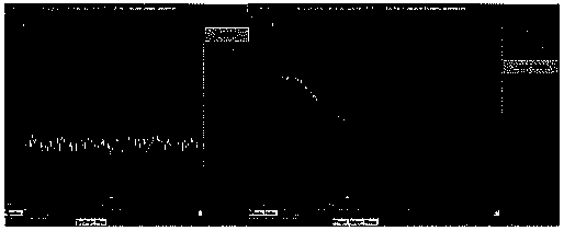
Figure 3
Abstract
Description
technical field
[0001] The invention relates to the technical field of millimeter wave / submillimeter wave frequency division in semiconductor technology, in particular to an injection-locked frequency divider based on a lange coupler feedback structure. Background technique
[0002] Millimeter waves have the advantages of high frequency, wide bandwidth, and large information capacity. They have great application value and market prospects in military radar systems, radio astronomy, space, and short-distance wireless high-speed transmission. And with the rapid development of modern silicon-based processes, processes such as CMOS and SiGeBiCMOS can be used in submillimeter wave / terahertz systems, which replace III-V semiconductor processes that are limited by high cost and low integration. In a high-frequency communication system, the performance of the high-stable frequency source provided by the phase-locked loop affects the performance of the entire system, and the frequenc...
Examples
Embodiment
[0029] Press as Figure 10 As shown, connect the circuit under test. Under different bias voltages, there will be different frequency locking ranges; such as Figure 11As shown, for 1.05V power supply, the frequency locking range is 135-138.8GHz; for 1.1V power supply, the frequency locking range is 136.3-141GHz; for 1.2V power supply, the frequency locking range is 141.2-144.2GHz; For 1.3V power supply, the frequency locking range is 143.8~146.6GHz; for 1.4V power supply, the frequency locking range is 145.5~148.2GHz; for 1.5V power supply, the frequency locking range is 147.4~149.4GHz; for 1.6 When powered by V voltage, the frequency locking range is 148.9-150.2GHz, while the power loss is only 14.4mW.
[0030] Such as Figure 12 As shown, when the input signal frequency is 135GHz, Vcc=1.6V, the size of the output signal is -5.6922dBm, the frequency is 25.033GHz; the phase noise is -121.5813dBc / Hz1MHz; Figure 13 As shown, when the input signal frequency is 150.2GHz, Vcc...