
One-step three-phase boosting matrix converter and topological structure thereof
A matrix converter and step-up technology, applied in the direction of converting AC power input to AC power output, output power conversion devices, electrical components, etc., can solve problems such as commutation complexity, and achieve safe switching and good output performance Effect
Patent Information
- Authority / Receiving Office
- CN · China
- Current Assignee / Owner
- Publication Date
- 2016-04-27
- Estimated Expiration
- Not applicable · inactive patent
Smart Images
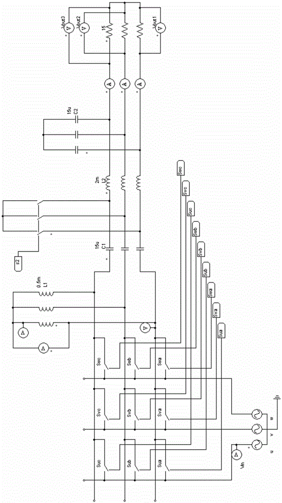
Figure 1 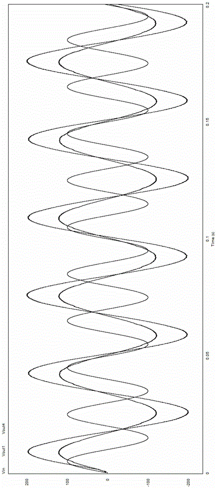
Figure 2 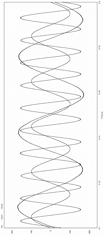
Figure 3
Abstract
Description
technical field
[0001] The invention is a one-step three-phase step-up matrix converter and its topological structure, and relates to the topological structure of a three-phase matrix converter and its corresponding control strategy and commutation strategy. Background technique
[0002] Today, AC speed regulation has become an important means of realizing automation and energy saving in electric drive systems, and plays an increasingly important role in industrial production. As the core of AC speed control system, AC conversion technology has become one of the most important research directions of power electronics and motion control technology. Matrix converter is an advanced electric energy converter, which has the advantages of arbitrary adjustment of output frequency, bidirectional flow of energy, no need for large-capacity energy storage components, and can control the phase of input current and output voltage arbitrarily, making the input power factor arbitrarily adj...
Examples
Embodiment Construction
[0014] In order to make the technical means, creative features, goals and effects achieved by the present invention easy to understand, the present invention will be further described below in conjunction with specific embodiments.
[0015] see Figure 1 to Figure 6 , the present invention provides a technical solution: a one-step three-phase step-up matrix converter and its topology, including a main loop, a control loop and a detection loop, the main loop is composed of a power switch drive circuit, a one-step matrix converter Converter frequency boosting circuit, output filter circuit and load, the control loop is composed of DSP real-time duty cycle calculation system, CPLD commutation logic control system, the detection loop is composed of voltage and current detection circuit and current direction detection circuit, The voltage and current detection circuit is connected with the DSP real-time duty cycle calculation system, the current direction detection circuit is conne...