
A fast pulse pressure method based on sparse inverse Fourier transform
A technology of inverse Fourier transform and Fourier transform, which is applied in the field of radar target detection signal processing, and can solve the problems of large amount of computation in the pulse pressure method
Patent Information
- Authority / Receiving Office
- CN · China
- Patent Type
- Patents(China)
- Current Assignee / Owner
- Publication Date
- 2018-10-16
- Estimated Expiration
- Not applicable · inactive patent
Smart Images
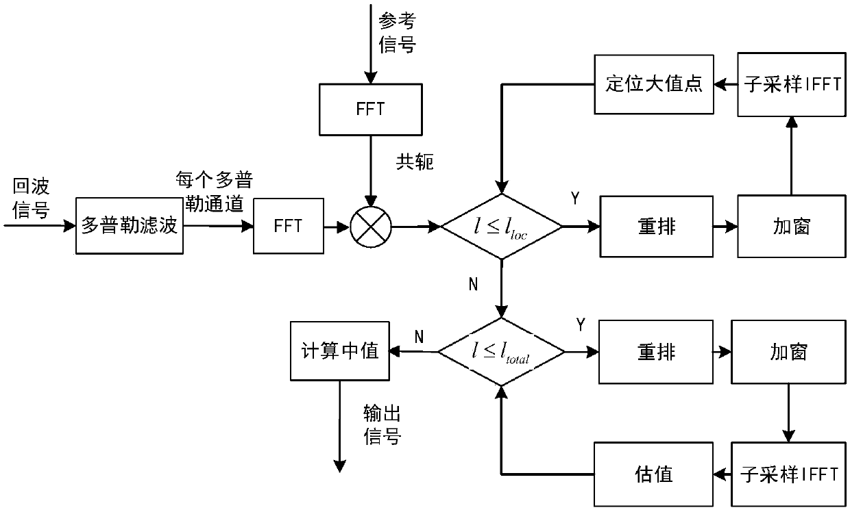
Figure 1 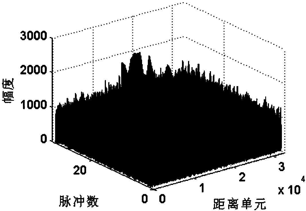
Figure 2 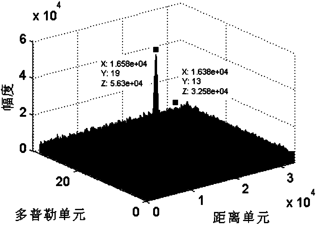
Figure 3
Abstract
Description
technical field
[0001] The invention relates to a fast pulse pressure method based on sparse inverse Fourier transform, belonging to the field of radar target detection signal processing. Background technique
[0002] Range resolution and maximum detection range are two key indicators to measure radar detection performance. The maximum detection distance is proportional to the average power emitted by the radar, so increasing the maximum detection distance requires increasing the pulse width, but the larger the pulse width, the lower the distance resolution. In order to solve the contradiction between radar detection range and range resolution, modern radars generally use large time-width bandwidth signals, and pulse compression is performed on echo signals at the receiving end to obtain better range resolution. Due to the development of digital electronic technology and the application of large-scale integrated circuits, the pulse compression processing system of linear fr...
Examples
Embodiment 1
[0063] This embodiment illustrates the process of applying the "a fast pulse pressure method based on sparse inverse Fourier transform" of the present invention to perform pulse pressure on two-component weak target echoes.
[0064] figure 1 It is the method flow chart of "a fast pulse pressure method based on sparse inverse Fourier transform" of the present invention and the flow chart of this embodiment.
[0065] from figure 1 It can be seen that this method includes the following steps:
[0066] Step A: calculating the reference signal spectrum;
[0067] Specifically to this embodiment, the reference signal is equal to the radar emission signal, and the radar parameters are set to: accumulated pulse number P=32, pulse width T p =260μs, pulse repetition period T=2ms, bandwidth B=10MHz, sampling rate f s = 15MHz;
[0068] Step B: Perform Doppler filtering on the echo signals of the two-component weak targets between pulses, and then perform FFT operations on all Doppler ...
Embodiment 2
[0080] In this embodiment, according to the parameter settings described in Embodiment 1, a computer simulation was carried out by using matlab. In the simulation experiment, this example simulates a two-component LFM signal to simulate the echo signal containing two weak targets.
[0081] The frequency domain pulse pressure is directly performed on the echo signal of the weak target, and the result is as follows figure 2 As shown, the X coordinate is the distance unit, the Y coordinate is the number of accumulated pulses, and the Z coordinate is the signal amplitude. It can be seen from the figure that the target signal is relatively weak, almost submerged in the noise, and its output signal-to-noise ratio is about 5.1dB. In this case, the SIFFT transformation cannot locate the position of the large-value point in the time domain, let alone estimate the magnitude of the large-value point. Therefore, SIFFT cannot be directly used to replace the IFFT in the frequency-domain pu...