
Supporting device for plastic pipe
A supporting device and plastic pipe technology, applied in metal processing, etc., can solve problems such as uneven end faces of pipes, failure to meet the use standards and requirements, and easy rotation of pipes, and achieve the effect of improving cutting quality
Patent Information
- Authority / Receiving Office
- CN · China
- Patent Type
- Applications(China)
- Current Assignee / Owner
- Publication Date
- 2017-02-22
- Estimated Expiration
- Not applicable · inactive patent
Smart Images
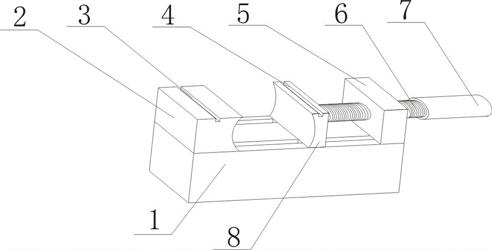
Figure 1 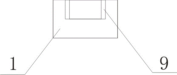
Figure 2
Abstract
Description
technical field
[0001] The invention relates to a supporting device for plastic pipes. Background technique
[0002] At present, the known plastic pipes are usually cut with a cutting machine, but in some specific construction applications, re-cutting is often involved. At this stage, most of them are cut manually with a saw. Due to the structural limitations of the pipe, During the cutting process, the pipe is easy to rotate and not fixed. The end face of the pipe cut by this operation is extremely uneven and produces a lot of burrs, resulting in non-compliance with the use standards and requirements, resulting in waste of resources. Contents of the invention
[0003] In order to solve the problems in the prior art, the purpose of the present invention is to provide a support device for plastic pipes.
[0004] In order to realize the above-mentioned purpose of the invention, the present invention adopts the technical scheme as follows:
[0005] A support device for a pl...
Examples
Embodiment Construction
[0015] The technical solutions of the present invention will be further described in detail below in conjunction with the accompanying drawings and embodiments.
[0016] Such as figure 1 , 2 As shown, a support device for a plastic pipe includes a base 1, a baffle 2, a clamp 8, a screw 6 and a screw seat 5, and one end on the upper surface of the base 1 is fixedly connected to the baffle 2, and on the upper surface of the base 1 The other end of the screw rod seat 5 is fixedly connected, and the screw rod seat 5 is provided with a threaded through hole, and the threaded through hole on the screw rod seat is equipped with a screw mandrel 6, and one end of the screw mandrel 6 is connected with a clamping plate 8, and the clamping plate The lower end surface of 8 is provided with two slide blocks, and slide block is adapted to be installed in the chute 9 that offers on the base upper surface.
[0017] On the upper end surface of the baffle plate 2 is provided a strip-shaped thr...