
Double-ended metal circular sawing machine
A circular saw machine and metal technology, applied in the mechanical field, can solve the problems of reducing machining accuracy and deviation, and achieve the effects of improving machining accuracy, low transmission error and convenient maintenance.
Patent Information
- Authority / Receiving Office
- CN · China
- Patent Type
- Applications(China)
- Current Assignee / Owner
- Publication Date
- 2017-10-03
Smart Images
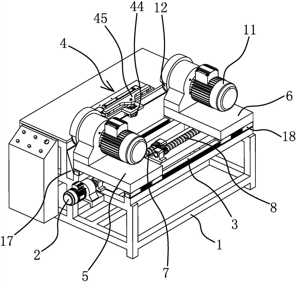
Figure 1 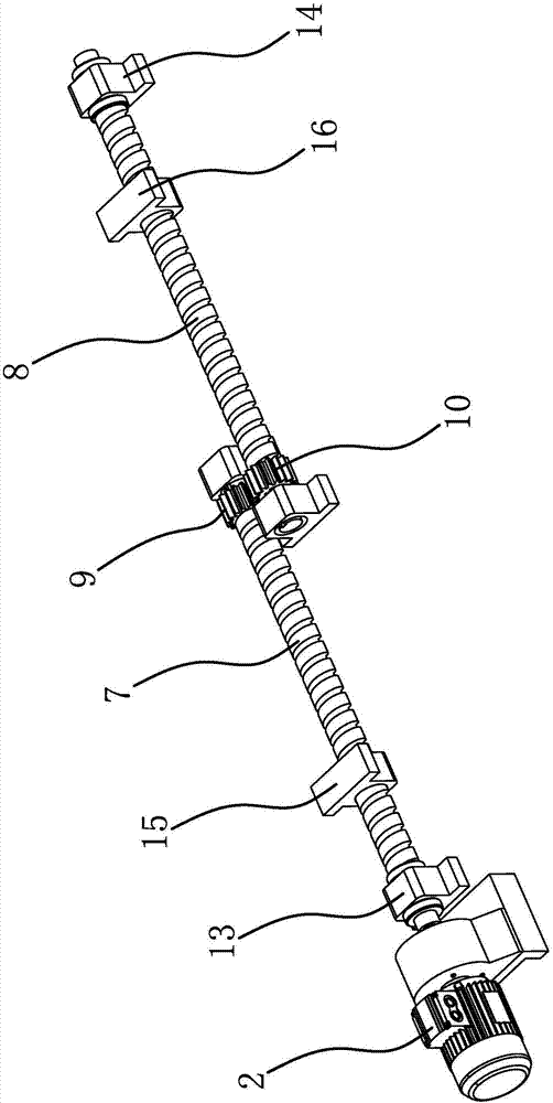
Figure 2 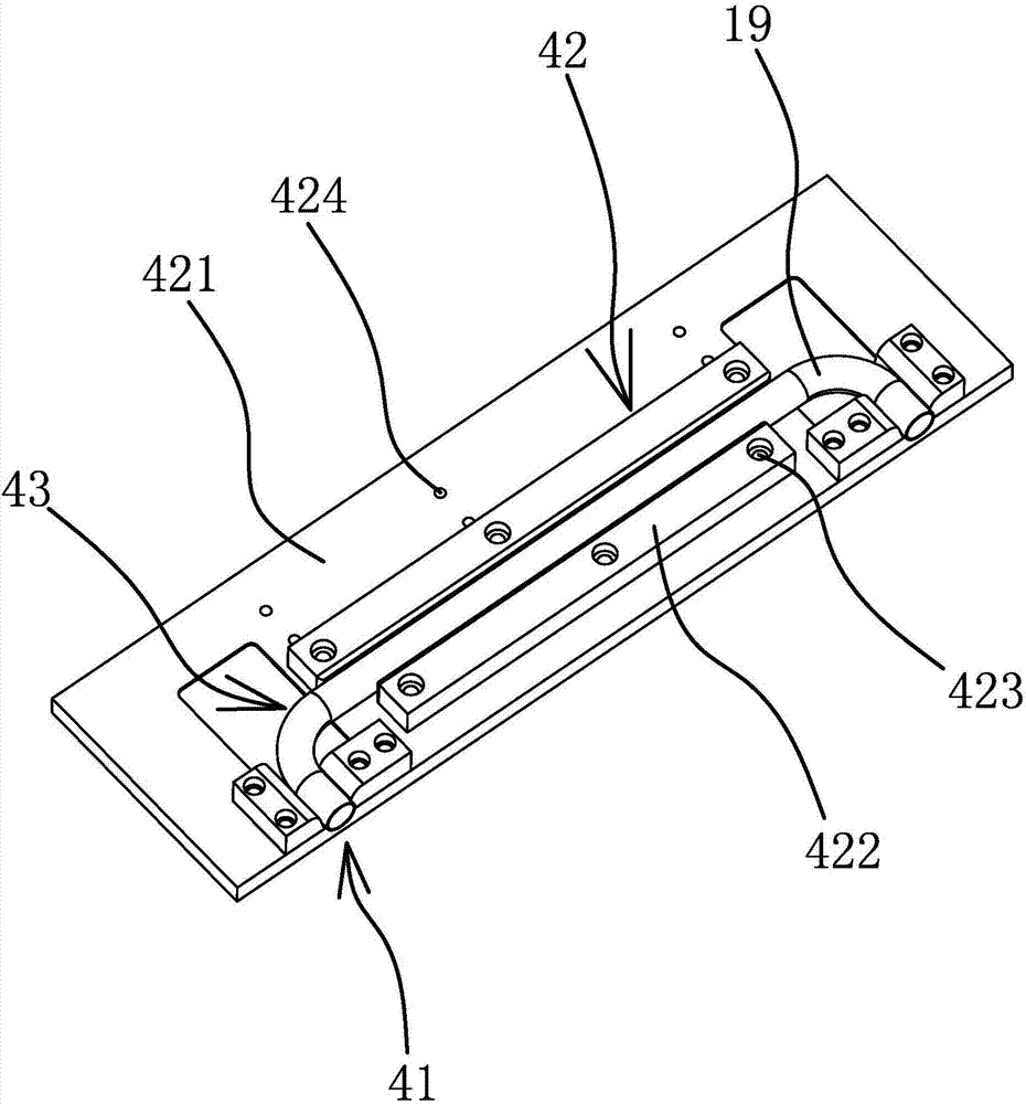
Figure 3
Abstract
Description
technical field
[0001] The invention belongs to the technical field of machinery and relates to a double-head metal circular saw machine. Background technique
[0002] Metal circular saws are widely used in pipe fitting hardware manufacturers. The products cut by metal circular saws have smooth cuts and no burrs. The quality of the cuts is basically close to wire cutting, and the production cost is only one tenth of wire cutting. However, at present The size locator randomly equipped with the metal circular saw machine is too simple, the positioning adjustment is troublesome, the positioning accuracy is poor, and the repeatability is poor.
[0003] In response to the above problems, people have made various improvements, and some have applied for patents. For example, Chinese patent literature discloses a positioning device for cutting bent pipes [application number: 201220058057.3; authorized announcement No.: CN202462071U], it comprises the main platen that is fixedly arr...
Examples
Embodiment 1
[0026] This double-head metal circular saw machine is mainly used for cutting the two ends of the elbow 19, such as figure 1 As shown, the double-head metal circular saw machine includes a frame 1, a driving source 2, a guide rail 3, a fixed structure 4, a first sliding plate 5, a second sliding plate 6, a first screw rod 7, a second screw rod 8, A first gear 9 , a second gear 10 , a drive motor 11 and a circular saw blade 12 .
[0027] The driving source 2 , the guide rail 3 and the fixing structure 4 are all fixedly connected to the frame 1 . The driving source 2 is a motor, and the number of guide rails 3 is a pair. The guide rails 3 are provided with a first sliding plate 5 and a second sliding plate 6, and the bottoms of the first sliding plate 5 and the second sliding plate 6 are fixedly connected with sliders. 18, the slider 18 is connected with the guide rail 3, the first sliding plate 5 and the second sliding plate 6 are provided with a driving motor 11, and the outp...
Embodiment 2
[0032] The structure and principle of this embodiment are basically the same as that of Embodiment 1, the difference is that in this embodiment, the fixed structure 4 includes a fixed frame 42, the top of the fixed frame 42 has a fixed groove 43, and both ends of the fixed groove 43 have The positioning notch 41 and the top of the fixing frame 42 are provided with a compression oil cylinder, the piston rod of the compression oil cylinder is fixedly connected with a compression plate 45 , and the compression plate 45 is located above the positioning notch 41 .
Embodiment 3
[0034] The structure and principle of this embodiment are basically the same as that of Embodiment 1, the difference is that in this embodiment, the first screw mandrel 7, the second screw mandrel 8 and the guide rail 3 are all arranged in the vertical direction, and the first screw mandrel 7 1. The second threaded mandrel 8 is parallel to the guide rail 3, the fixed structure 4 is located on one side of the guide rail 3, and the feeding mode of the circular saw blade 12 is to feed up and down along the vertical direction.