
LED area light source reciprocating control device for glue spreader
A technology of LED surface light source and control device, which is applied in the direction of surface coating liquid device, coating, pretreatment surface, etc., which can solve the problem of low curing efficiency of glue coating
Patent Information
- Authority / Receiving Office
- CN · China
- Current Assignee / Owner
- Publication Date
- 2018-07-10
- Estimated Expiration
- Not applicable · inactive patent
Smart Images
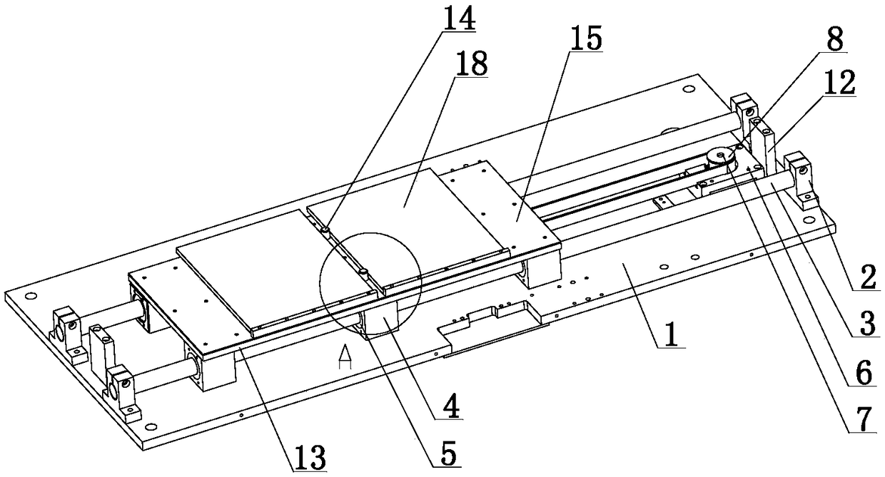
Figure 1 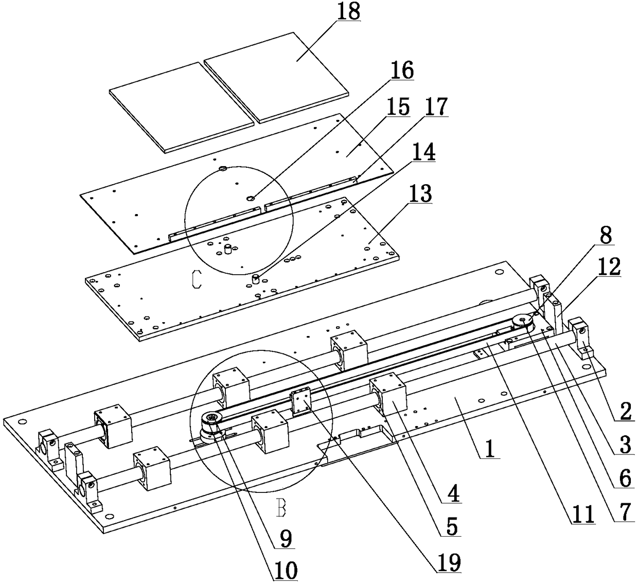
Figure 2 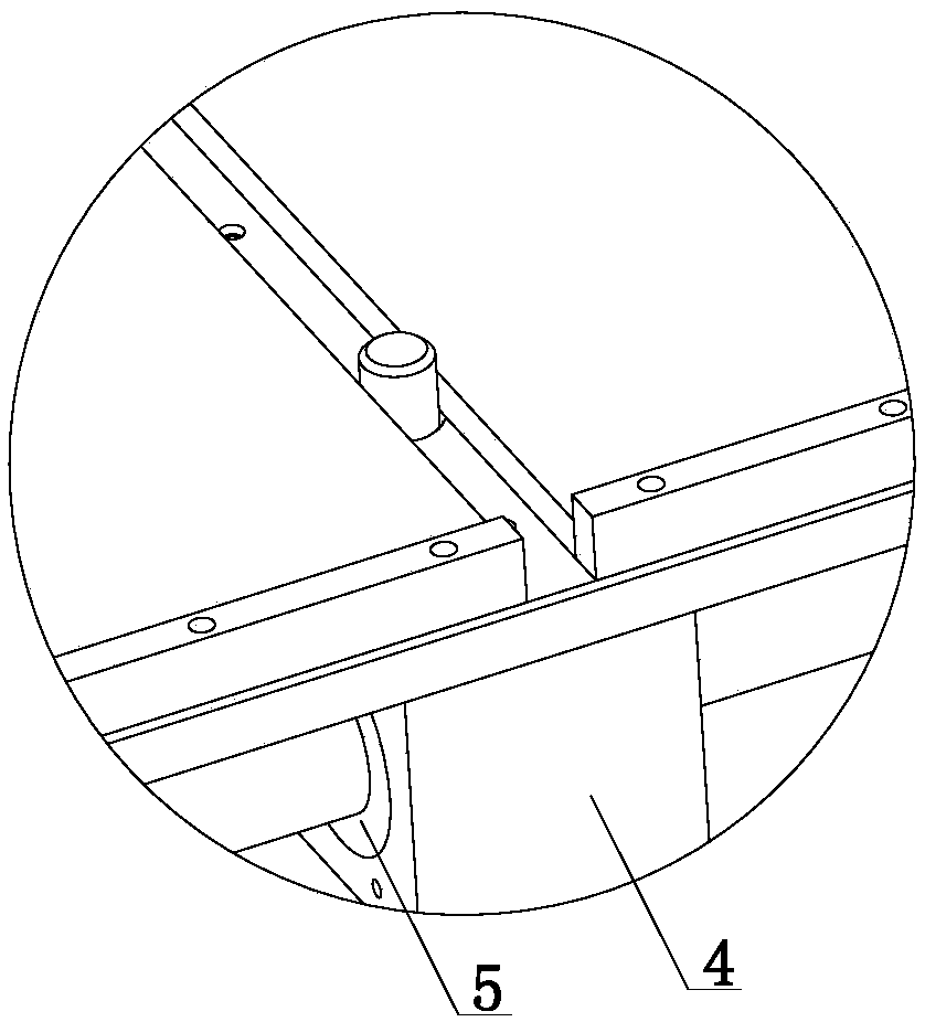
Figure 3
Abstract
Description
technical field
[0001] The invention relates to a control device, in particular to a reciprocating control device for an LED surface light source used in a gluing machine. Background technique
[0002] Glue applicator, also known as coating machine, glue scraping machine, automatic glue spraying machine, is a kind of mechanical equipment mainly used to apply liquid glue on the surface of textiles, cartons or leather. There are many kinds of glue applicators. Styles, such as: drum gluer, double-action gluer, double-station lifting gluer. The inner bottom of the existing gluing machine is not equipped with a surface light source mechanism, and the curing efficiency of the gluing layer of the gluing machine is low. Contents of the invention
[0003] The present invention mainly solves the technical problems existing in the prior art, thereby providing a reciprocating mechanism that can control the moving plate to realize the reciprocating movement; the moving plate controls ...
Examples
Embodiment Construction
[0018] The preferred embodiments of the present invention will be described in detail below in conjunction with the accompanying drawings, so that the advantages and features of the present invention can be more easily understood by those skilled in the art, so as to define the protection scope of the present invention more clearly.
[0019] Such as Figure 1 to Figure 7 As shown, a LED surface light source reciprocating control device for a gluing machine includes a base plate 1, a pair of fixing seats 2 are provided at both ends of the base plate 1, a guide shaft 3 is provided between the fixing seats 2, and the guide shaft 3 A plurality of sliding seats 4 are set on the outer peripheral surface, a fixed seat 6 is provided on one end of the base plate 1, a fixed shaft 7 is arranged on the fixed seat 6, a rotating wheel 8 is set on the outer peripheral surface of the fixed shaft 7, and the other end of the base plate 1 is provided with The driven shaft 9, the end of the drive...