
Method for intelligent fault inference of inverter
An inverter and fault technology, applied in the field of inverter intelligent fault reasoning, can solve problems such as difficulty in fault symptom information, poor applicability of diagnosis methods, and inaccurate diagnosis results.
Patent Information
- Authority / Receiving Office
- CN · China
- Patent Type
- Applications(China)
- Current Assignee / Owner
- Publication Date
- 2019-03-26
Smart Images
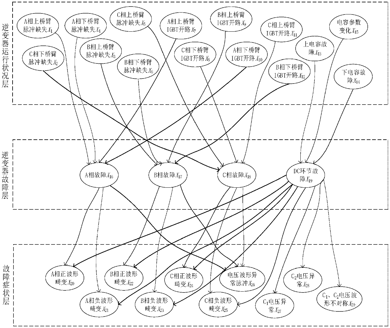
Figure 1 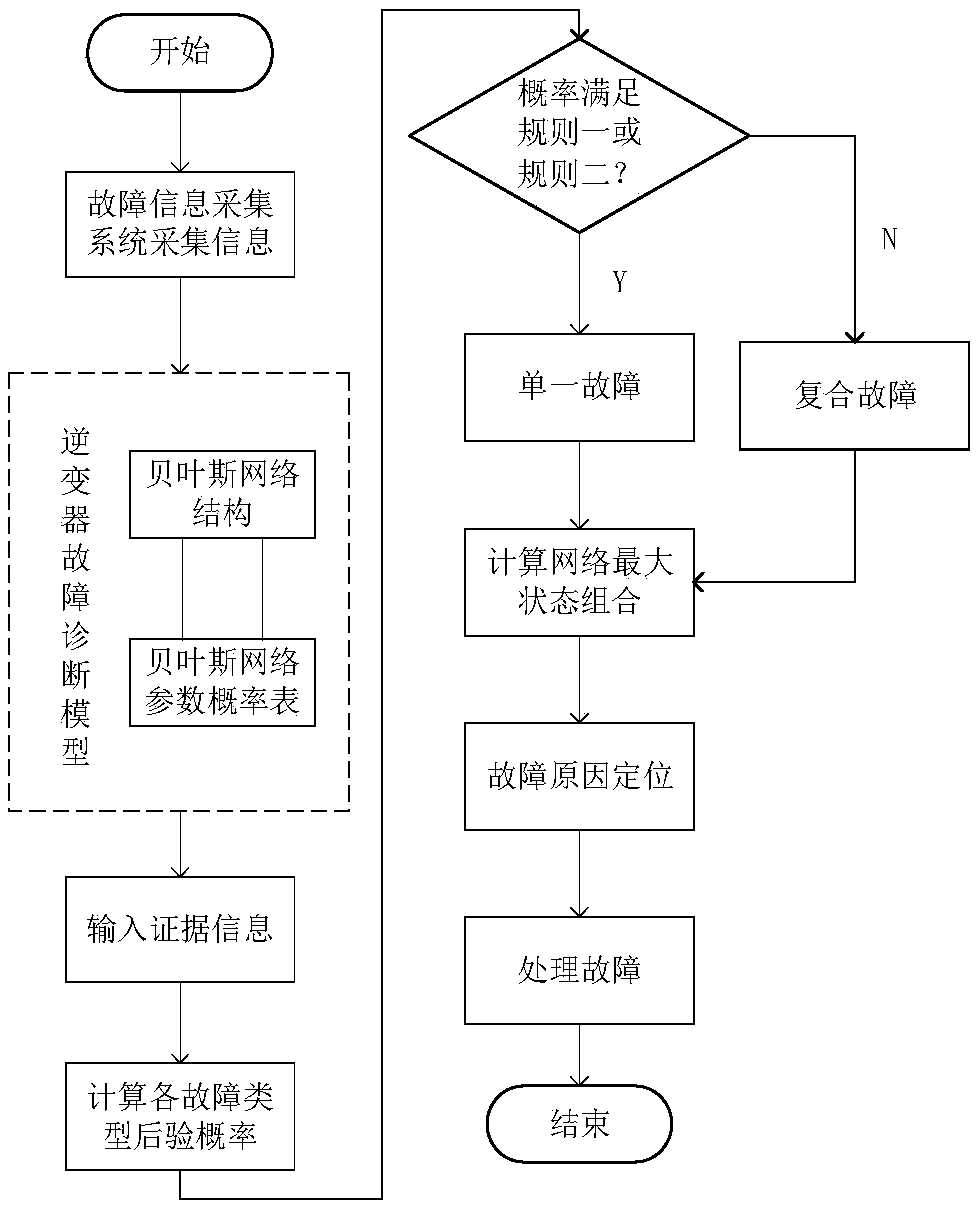
Figure 2 
Figure 3
Abstract
Description
technical field
[0001] The invention relates to the technical field of fault diagnosis in the electric power field, in particular to a method for intelligent fault reasoning of an inverter. Background technique
[0002] The existing inverter fault reasoning and diagnosis methods are mainly divided into four categories, one is the method based on neural network, the other is the expert system method, the third is the fault tree mode diagnosis method, and the fourth is the method based on comparative detection. The neural network-based method obtains fault data through sensors, and interprets the encoded data of sensors through neural networks. The expert system method is to establish a knowledge base, and judge the type of fault by querying the knowledge base by observing the fault phenomenon. The fault tree model diagnosis method is to establish a fault tree and carry out fault diagnosis through algorithms. The method based on comparing the detection quantity is to diagnos...
Examples
Embodiment 1
[0091] Insufficient evidence information in Example 1
[0092] combined with figure 1 , the symptom information collected by the fault information collection system includes: Phase B negative waveform distortion occurs (X 23 = 2) and C-phase positive waveform distortion occurs (X 24 =2).
[0093] The single failure probability data of the failure layer calculated by formula (8) is:
[0094] P(X 16 =2|X 23 =2,X 24 = 2) = 15.02%
[0095] P(X 17 =2|X 23 =2,X 24 = 2) = 25.29%
[0096] P(X 18 =2|X 23=2,X 24 = 2) = 32.25%
[0097] P(X 19 =2|X 23 =2,X 24 = 2) = 52.87%
[0098] The probability of failure in the DC link is the highest, and then the single failure probability is ruled out, P(X 19 =2|X 23 =2,X 24 =2)-P(X 18 =2|X 23 =2,X 24 =2)=20.62%>20%, this case satisfies rule 2, and the fault type is judged to be a single fault, so it can be judged that the inverter fault is a DC link fault (X 19 ).
[0099] The parent node of the DC link fault is: the upper...
Embodiment 2
[0104] Example 2 Evidence information conflict
[0105] combined with figure 1 , the symptom information collected by the fault information collection system includes: Phase A negative waveform distortion occurs (X 21 =2), B-phase positive waveform distortion does not occur (X 21 =1) and B-phase negative waveform distortion occurs (X 23 = 2), it is found by inspection that the lower bridge arm pulse of the B phase is absent (X 6 =2). Judging from the evidence presented, this case is a case of conflict of evidence. Evidence comes from the inverter health layer and the fault symptom layer. Evidence from health layer Phase B lower arm pulse missing (X 6 ) indicates that there is a phase B fault (X 17 ), but this conclusion is not supported by the fault symptom layer.
[0106] The single failure probability data of the failure layer calculated by formula (8) is:
[0107] P(X 16 =2|X 6 =1,X 21 =2,X 22 =2,X 23 = 2) = 24.51%
[0108] P(X 17 =2|X 6 =1,X 21 =2,X 22 =...