
High-voltage power supply device
A high-voltage power supply and piezoelectric transformer technology, applied in the direction of output power conversion devices, electrical components, printing, etc., can solve problems such as difficulty in obtaining high-quality images, unstable output voltage, etc., and achieve improved image transfer quality and stability Output voltage control, effect of reducing distortion
Patent Information
- Authority / Receiving Office
- CN · China
- Current Assignee / Owner
- Publication Date
- 2019-10-08
- Estimated Expiration
- Not applicable · inactive patent
Smart Images
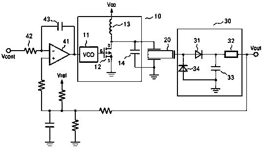
Figure 1
Abstract
Description
technical field
[0001] The invention relates to a high-voltage power supply device, belonging to the field of power supplies. Background technique
[0002] In the image transfer process of laser printers or copiers, image transfer is achieved by applying voltage to the transfer roller. In order to achieve a good transfer effect, a high voltage (several hundred volts higher than the voltage of a commercial power supply) and a current of about 10 μA need to be applied to the transfer roller.
[0003] To generate such high voltages, wire-wound electromagnetic transformers have traditionally been used. However, the electromagnetic transformer is bulky and heavy, which is an obstacle to reducing the size and weight of the high-voltage power supply device. Therefore, research began on the use of piezoelectric transformers (piezoelectric ceramic transformers). With the piezoelectric transformer, a high voltage can be generated with higher efficiency than the electromagnetic tran...
Examples
Embodiment Construction
[0015] The present invention will be described in detail below in conjunction with the accompanying drawings and specific embodiments.
[0016] see figure 1 , a high-voltage power supply device, comprising a driving unit 10, a piezoelectric transformer 20 and a smoothing processing unit 30, the output of the driving unit 10 drives the piezoelectric transformer 20, and the smoothing processing unit 30 includes a high-voltage diode 31, a first resistor 32 and a first capacitor 33, the anode of the high voltage diode 31 is connected to the output terminal of the piezoelectric transformer 20, and the cathode of the high voltage diode 31 is respectively connected to the first resistor 32 and the first A capacitor 33, the first capacitor 33 is grounded, and the other end of the first resistor 32 is an output end. The output terminal of the piezoelectric transformer 20 is also connected to a reverse protection diode 34 .
[0017] The driving unit 10 includes a voltage-controlled os...