
Power amplifier circuit
Patent Information
- Authority / Receiving Office
- US · United States
- Current Assignee / Owner
- Publication Date
- 2020-10-29
Smart Images
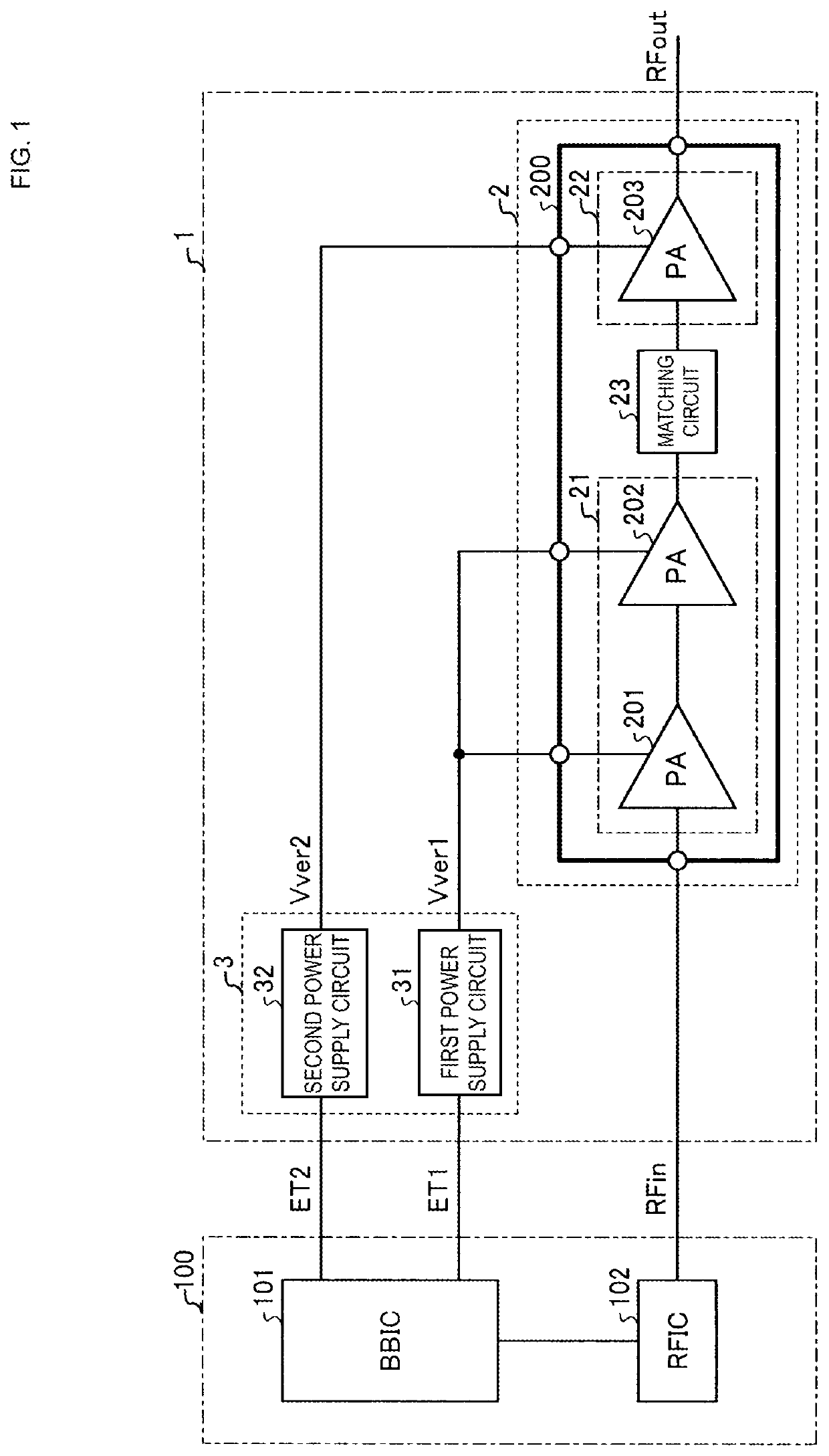
Figure 1 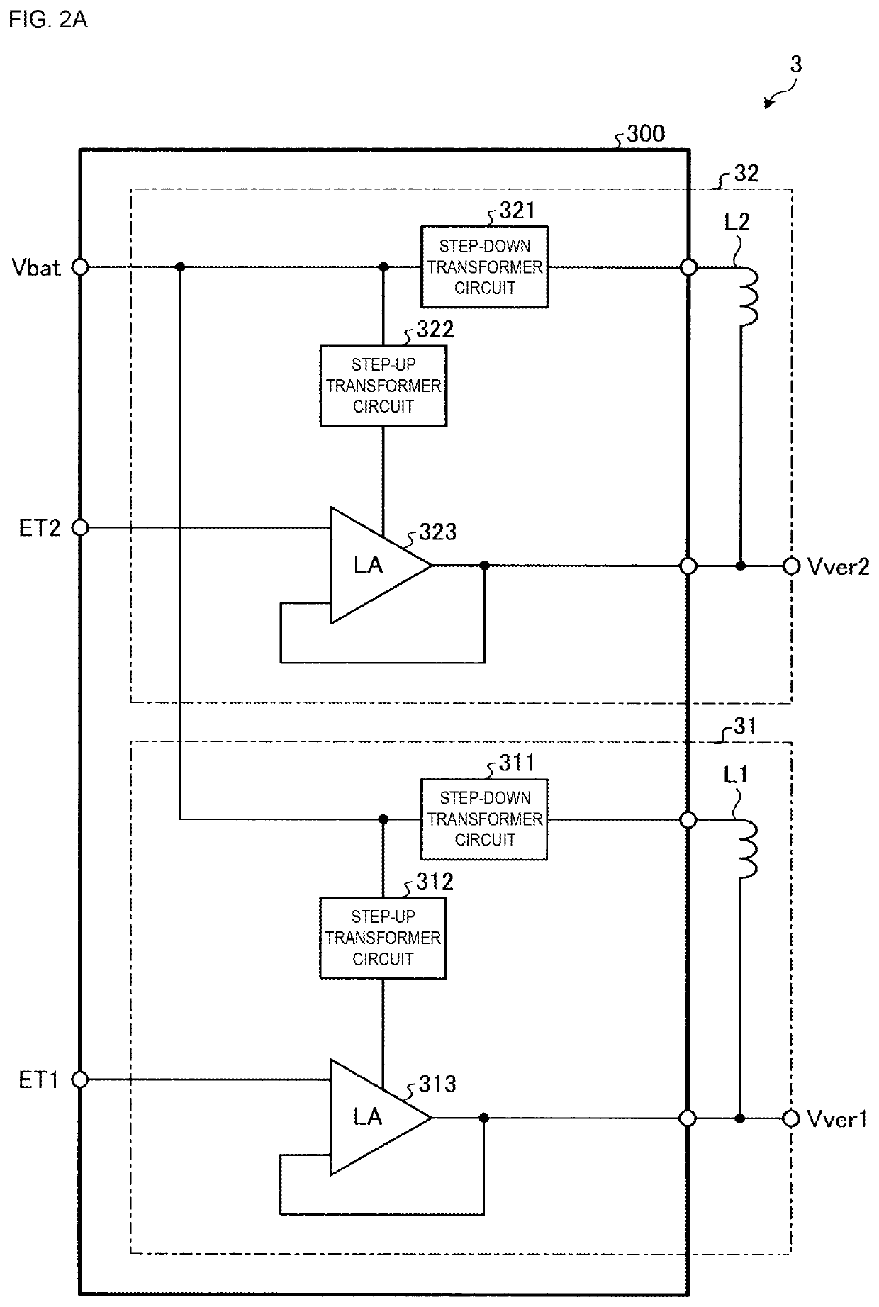
Figure 2 
Figure 3
Abstract
Description
[0001] This application claims priority from Japanese Patent Application No. 2019-083359 filed on Apr. 24, 2019. The content of this application is incorporated herein by reference in its entirety.BACKGROUND
[0002] The present disclosure relates to a power amplifier circuit.
[0003] Examples of technology for increasing the efficiency of a power amplifier circuit mounted on a wireless communication terminal include envelope tracking (ET), which improves power efficiency by controlling the power supply voltage of a power amplifier according to the amplitude level of an input signal, and average power tracking (APT), which improves power efficiency by controlling the power supply voltage of a power amplifier according to the average output power. In general, envelope tracking achieves greater power efficiency than average power tracking when the output voltage of the power amplifier is great, and average power tracking achieves greater power efficiency than envelope tracking when the output...
Examples
first embodiment
[0026]FIG. 1 is a diagram illustrating the configuration of a power amplifier circuit according to the first embodiment. A power amplifier circuit 1 according to the first embodiment is mounted on, for example, a wireless communication terminal that supports radio frequency (RF) communication using Sub 6 of the fifth-generation mobile communication system or the 5 GHz frequency band of Wi-Fi.
[0027]The power amplifier circuit 1 amplifies an RF input signal RFin input from a radio-frequency integrated circuit (RFIC) 102 of a controller 100, and outputs an RF output signal RFout. As illustrated in FIG. 1, the power amplifier circuit 1 according to the first embodiment includes an amplifier (first amplifier or first amplifier unit) 2 and a power supply circuit 3.
[0028]In the amplifier (first amplifier) 2, a former amplifier 21 and a latter amplifier 22 are connected in series with a matching circuit 23 interposed therebetween. The former amplifier 21 includes power amplifiers (PAs) 201 ...
second embodiment
[0068]FIG. 5 is a diagram illustrating the configuration of a power amplifier circuit according to a second embodiment. FIG. 6 is a diagram illustrating the configuration of a power amplifier circuit according to a modification of the second embodiment. The power amplifier circuit may have the configuration illustrated in FIG. 5 or the configuration illustrated in FIG. 6 depending on the gain distribution of the power amplifiers (PAs) 201, 202, and 203. Note that the same elements as those of the first embodiment are given the same reference symbols, and descriptions thereof are omitted.
[0069]In a power amplifier circuit 1b of the second embodiment and a power amplifier circuit 1c of the modification of the second embodiment, a matching circuit 24 provided between the former amplifiers 21 and 21a and the latter amplifiers 22 and 22a of amplifiers (first amplifiers) 2b and 2c includes a band-pass filter (BPF). The matching circuit 24 is included in power amplifier modules (PAMs) 200b...
third embodiment
[0072]In a third embodiment, the configuration including a plurality of amplifiers and realizing multi-band and broadband communication will be discussed. FIG. 7 is a diagram illustrating a first example of the schematic configuration of a power amplifier circuit according to a third embodiment. FIG. 8 is a diagram illustrating a second example of the schematic configuration of the power amplifier circuit according to the third embodiment. FIG. 9 is a diagram illustrating a third example of the schematic configuration of the power amplifier circuit according to the third embodiment. FIG. 10 is a diagram illustrating a fourth example of the schematic configuration of the power amplifier circuit according to the third embodiment. FIG. 11 is a diagram illustrating a fifth example of the schematic configuration of the power amplifier circuit according to the third embodiment. FIG. 12 is a diagram illustrating a sixth example of the schematic configuration of the power amplifier circuit ...