
An automatic packaging device for capacitors
A technology for packaging devices and capacitors, which is applied in the direction of packaging capacitor devices, fixed capacitor shells/packages, capacitors, etc., which can solve the problems of increased packaging difficulty, poor moisture resistance and gas barrier properties, and increased residual products, so as to save human resources. , avoid manual participation, and improve the effect of yield rate
Patent Information
- Authority / Receiving Office
- CN · China
- Patent Type
- Patents(China)
- Current Assignee / Owner
- Publication Date
- 2021-12-03
Smart Images
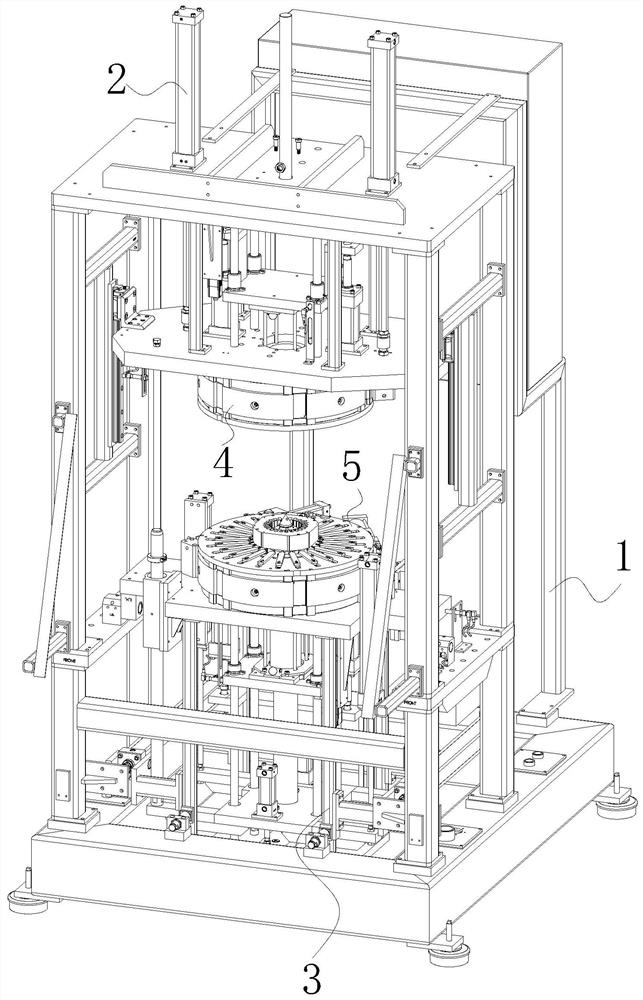
Figure 1 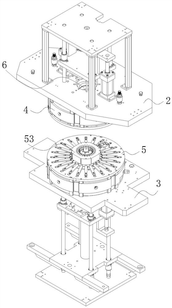
Figure 2 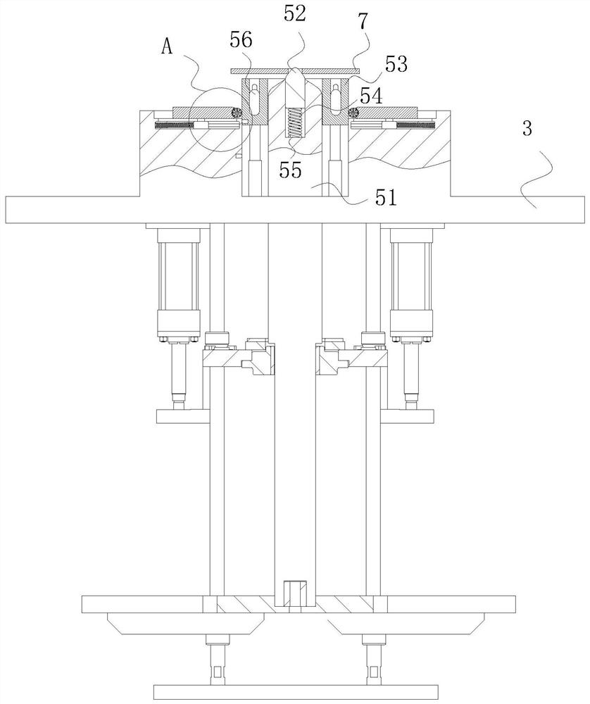
Figure 3
Abstract
Description
technical field
[0001] The invention belongs to the technical field of capacitor production and processing, in particular to an automatic packaging device for capacitors. Background technique
[0002] Two conductors close to each other, sandwiching a layer of non-conductive insulating medium, constitute a capacitor. When a voltage is applied between the two plates of the capacitor, the capacitor will store charge, and the capacitance of the capacitor is numerically equal to the ratio of the amount of charge on a conductive plate to the voltage between the two plates. The basic unit of capacitance of a capacitor is Farad (F), and the letter C is usually used to represent a capacitive element in a circuit diagram. Capacitors play an important role in tuning, bypassing, coupling, filtering and other circuits. It is used in the tuning circuit of transistor radio, and in the coupling circuit and bypass circuit of color TV.
[0003] In order to meet the needs of the structure, ...
Examples
Embodiment Construction
[0021] use Figure 1-Figure 5 An automatic packaging device for capacitors according to an embodiment of the present invention will be described as follows.
[0022] like Figure 1-Figure 5 As shown, a capacitor automatic packaging device according to the present invention includes a main body 1, an upper mounting frame 2, a lower mounting frame 3, an upper fixing block 4 and a lower fixing block 5; the upper end of the main body 1 is slidably connected with an upper mounting frame 2, the lower end of the main body 1 is slidingly connected with a lower mounting frame 3; the interior of the upper mounting frame 2 is fixedly installed with an upper fixing block 4; the inside of the upper fixing block 4 is provided with an insertion hole 6; the lower mounting The inside of the frame 3 is fixedly installed with a lower fixing block 5, and the lower mounting frame 3 is located directly below the upper mounting frame 2; A mounting rod 51 is slidably installed; the upper end of the...