
Kinematic pair joint gap eliminating mechanism for feeding robot and implementation method of kinematic pair joint clearance eliminating mechanism
A joint gap and robot technology, applied in manipulators, program-controlled manipulators, manufacturing tools, etc., can solve the problems of simultaneous elimination, general use effect, and affecting the normal operation of equipment, so as to improve stability and durability and eliminate kinematic joints gap effect
Patent Information
- Authority / Receiving Office
- CN · China
- Current Assignee / Owner
- Publication Date
- 2020-10-02
Smart Images
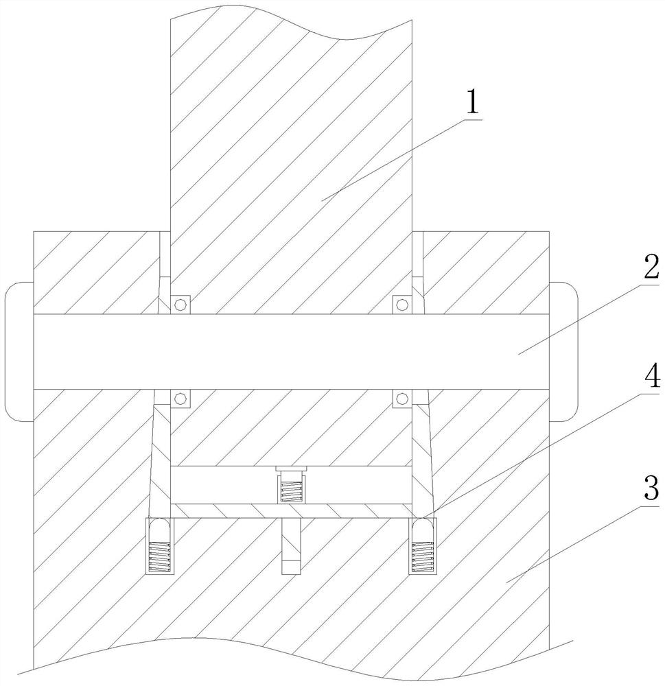
Figure 1 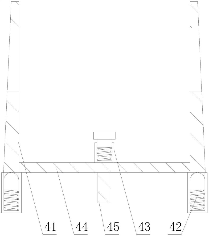
Figure 2 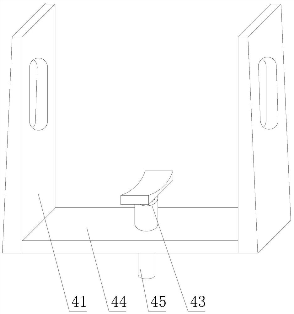
Figure 3
Abstract
Description
technical field
[0001] The invention relates to a kinematic sub-joint adjustment structure of a loading and unloading robot, in particular to a kinematic sub-joint gap elimination mechanism of a loading robot and an implementation method thereof. Background technique
[0002] The loading and unloading robot can meet the requirements of "fast / mass processing cycle", "saving labor costs" and "improving production efficiency", and has become an ideal choice for more and more factories. A kinematic pair is an active connection in which two components are in direct contact and can produce relative motion. Elements such as points, lines, and surfaces that participate in the contact of two components and form a kinematic pair are called kinematic pair elements. At the junction of the kinematic joints of the loading and unloading robot, there are often different parts that cooperate, but after the parts are matched for a long time, their wear increases, and there is a gap at the ki...
Examples
Embodiment approach
[0033]The implementation method of the kinematic pair joint gap elimination mechanism of the feeding robot includes the following steps:
[0034] The first step: first install the first compensation structure 42 in the compensation assembly 4 at a predetermined position in the inner cavity of the base arm 3, wherein the first compensation structure 42 is symmetrically installed in the inner cavity of the base arm 3;
[0035] Step 2: install the remaining parts in the compensation assembly 4 in the inner cavity of the base arm 3, wherein it is necessary to ensure that the bottom surface of the compensation plate 41 is in contact with the first compensation structure 42, and after the entire compensation assembly 4 is installed, it must be ensured that it will not Affect the normal operation of the swing arm 1, the transverse circular shaft 2 and the base arm 3;
[0036] Step 3: Then install the swing arm 1 to the predetermined position, wherein the swing arm 1 needs to be froze...