
Bionic glasses
A technology for bionic glasses and frames, applied in the field of bionic glasses, can solve problems such as reducing the incidence of eye diseases, no eye diseases, and inability to adjust, and achieves the goal of preventing eye fatigue, preventing excessive shaking, and ensuring stability. Effect
Patent Information
- Authority / Receiving Office
- CN · China
- Current Assignee / Owner
- Publication Date
- 2021-02-26
Smart Images
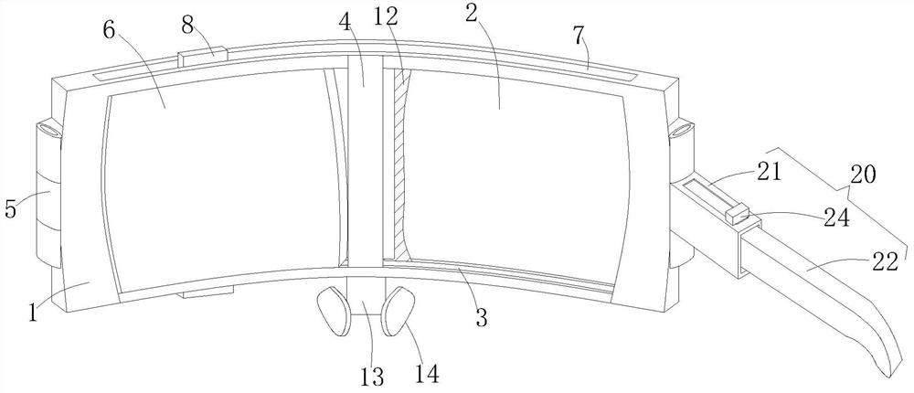
Figure 1 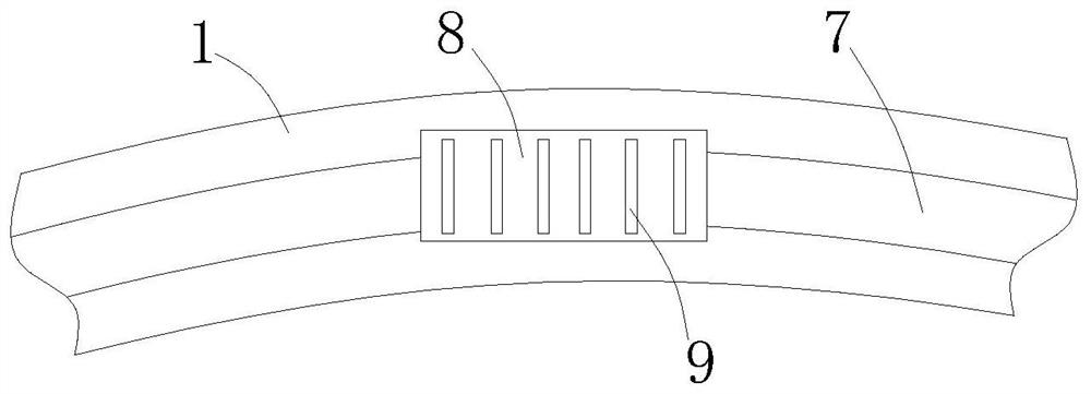
Figure 2 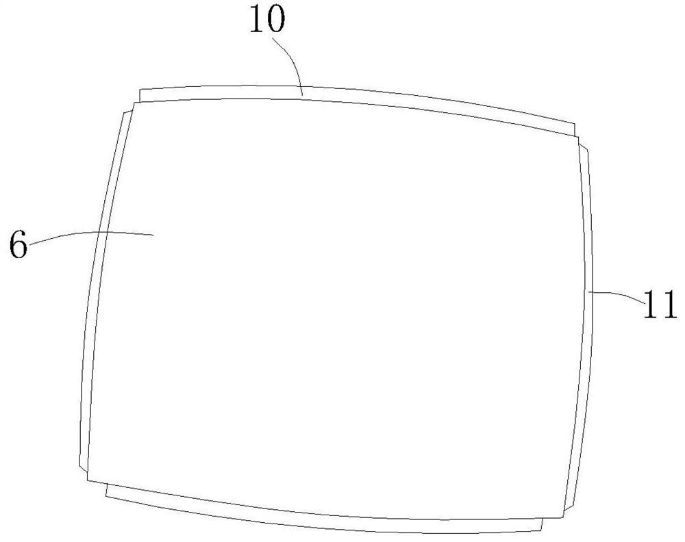
Figure 3
Abstract
Description
technical field
[0001] The patent of the present invention relates to the technical field of glasses, in particular, to bionic glasses. Background technique
[0002] Eye fatigue is a common disease in ophthalmology. It causes dry eyes, astringent eyes, sore eyes, blurred vision and even decreased vision directly affects people's work and life. Eye fatigue is mainly due to the fact that when people are concentrating on watching computer screens, working or studying, the number of eye blinks decreases, resulting in a corresponding decrease in tear secretion, and at the same time, flickering screens strongly stimulate the eyes. It can cause pain in the corresponding parts of the neck, shoulders, etc., and can also cause and aggravate various eye diseases. There are various ways to relieve eye fatigue, such as: ① Take more rest; ② Supplement vitamins; ③ Use eye drops and do eye exercises. These methods are nothing more than two aspects: relaxation and nutrition. Relaxation ca...
Examples
Embodiment Construction
[0025] In order to make the object, technical solution and advantages of the present invention clearer, the present invention will be further described in detail below in conjunction with the accompanying drawings and embodiments. It should be understood that the specific embodiments described here are only used to explain the present invention, not to limit the present invention.
[0026] The implementation of the present invention will be described in detail below in conjunction with specific embodiments.
[0027] In the drawings of this embodiment, the same or similar symbols correspond to the same or similar components; The indicated orientation or positional relationship is based on the orientation or positional relationship shown in the drawings, and is only for the convenience of describing the present invention and simplifying the description, rather than indicating or implying that the referred device or element must have a specific orientation, or in a specific orien...