
Rubber vulcanizing device for cable production line
A rubber vulcanization and production line technology, which is applied in transportation and packaging, cable/conductor manufacturing, electrical components, etc., can solve the problem of low vulcanization efficiency and achieve the effect of uniform vulcanization operation
Patent Information
- Authority / Receiving Office
- CN · China
- Current Assignee / Owner
- Publication Date
- 2021-03-16
- Estimated Expiration
- Not applicable · inactive patent
Smart Images
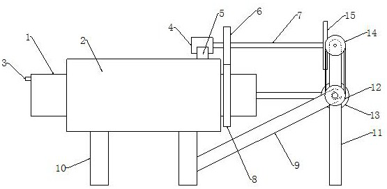
Figure 1 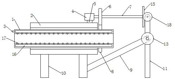
Figure 2 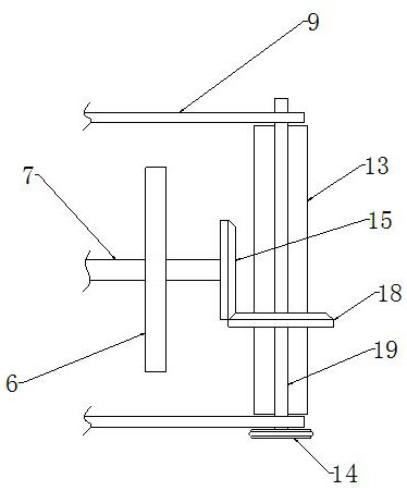
Figure 3
Abstract
Description
technical field
[0001] The invention relates to the field of cable production, in particular to a rubber vulcanizing device for a cable production line. Background technique
[0002] Rubber is one of the three major polymer materials. High elasticity is its characteristic. High elasticity endows rubber and rubber products with greater deformation under a small external force within a certain temperature range. When the external force disappears, it can Restore the original shape at an accelerated speed, which makes the rubber have the characteristics of cushioning, shock absorption, sound absorption, sealing, softness and flexibility. At the same time, most rubbers are also insulating, heat insulating, cold resistant, acid and alkali resistant, etc. Rubber can be used to manufacture tires, tapes, hoses, rubber shoes, seals, shock absorbers, insulating parts, adhesives, etc.
[0003] The skin of the cable is generally made of rubber, which needs to be vulcanized during the c...
Examples
Embodiment Construction
[0020] The following will clearly and completely describe the technical solutions in the embodiments of the present invention with reference to the accompanying drawings in the embodiments of the present invention. Obviously, the described embodiments are only some, not all, embodiments of the present invention.
[0021] refer to figure 1 and 2 , a rubber vulcanization device for a cable production line, including an inner cylinder 1, an outer cylinder 2 and a support column 10, the outer cylinder 2 and the inner cylinder 1 are arranged through each other, and the inner cylinder 1 is rotatably installed inside the outer cylinder 2, so The bottom end of the outer cylinder 2 is fixedly equipped with a support column 10, and the top end of the outer cylinder 2 is fixedly installed with a driving motor 4, and the output shaft of the driving motor 4 is fixedly connected with a rotating rod 7, and the rotating rod 7 The circumferential side wall of the inner cylinder 1 is fixedly s...