
Optical sensor device, sensor apparatus, cable and method of manufacturing
a sensor and optical sensor technology, applied in the field of optical sensor devices, can solve the problems of manufacturing, performance and handling problems becoming prohibitive, and the minimum stiffness setting a limit to the obtainable sensitivity, and achieve the effect of stable deflection position
Patent Information
- Authority / Receiving Office
- US · United States
- Patent Type
- Patents(United States)
- Current Assignee / Owner
- Publication Date
- 2019-10-22
Smart Images
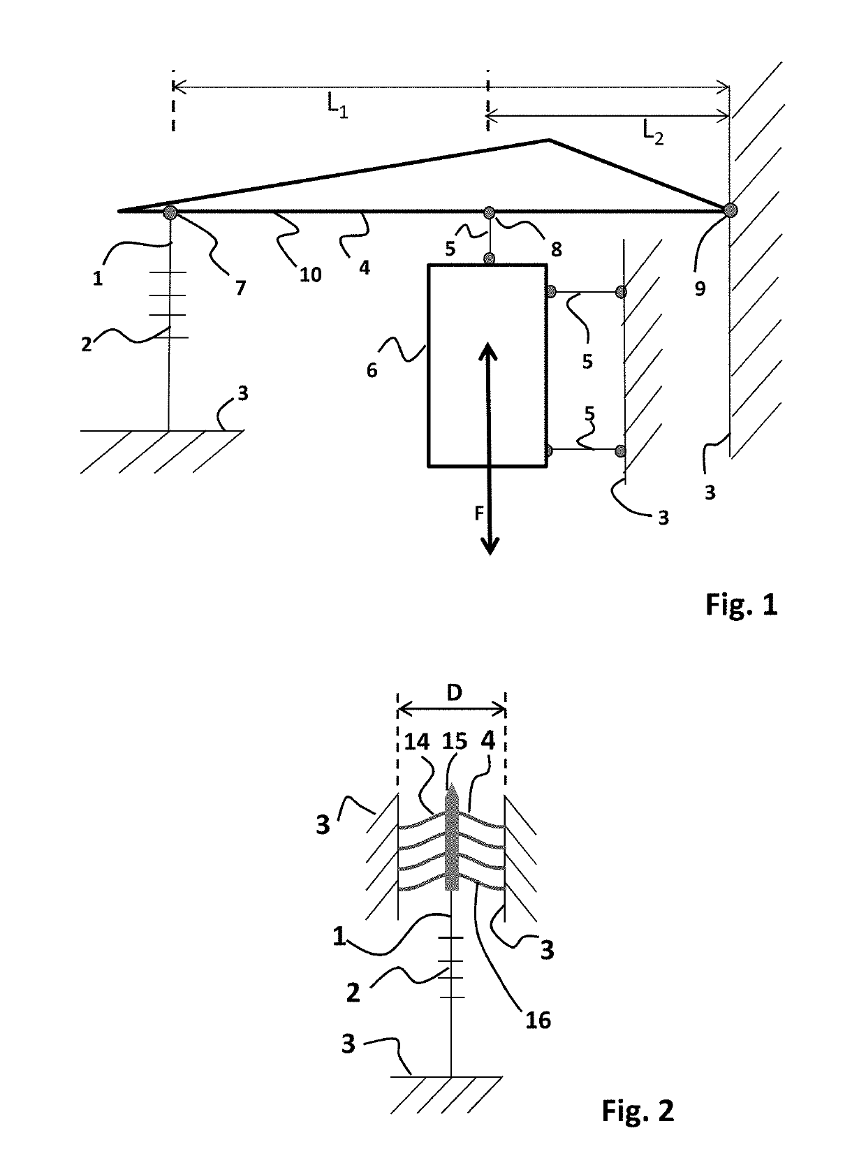
Figure 1 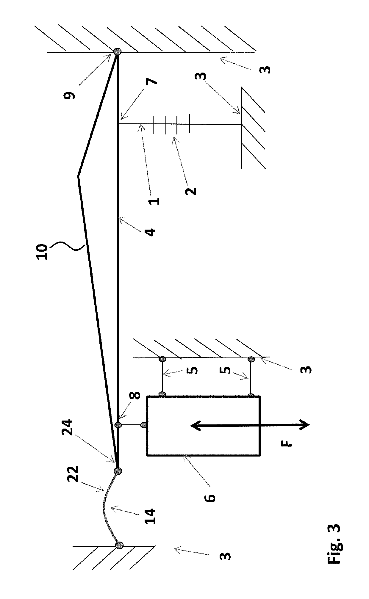
Figure 2 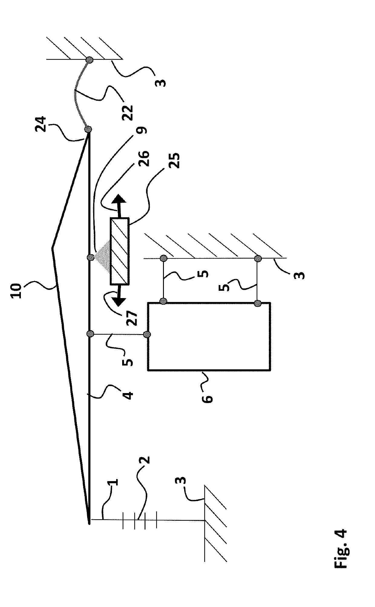
Figure 3
Abstract
Description
CROSS-REFERENCE TO RELATED APPLICATIONS
[0001] This application is a national stage application of International Application No. PCT / NL2015 / 050320, which was filed on May 8, 2015, of which is incorporated by reference in its entirety.FIELD OF THE INVENTION
[0002] The present invention relates to an optical sensor device, in particular an optical sensor device applying an intrinsic fiber optic sensor. The invention further relates to a method of manufacturing.BACKGROUND
[0003] A known class of optical sensors for various applications includes the use of intrinsic fiber optic sensors. An intrinsic fiber optic sensor is a sensor that uses an optical fiber as sensing element. In many applications the intrinsic fiber optic sensor is lit (e.g. by a laser), and a change in the fiber due to an external cause (dependent on the type of sensor) results in a measurable change in the optical signal transmitted by or received from the sensor. A typical example of an intrinsic fiber optic sensor is a Fi...
Examples
Embodiment Construction
[0038]The advantages of the optical sensor device of present invention may become more clear by considering the sensitivity of an optical accelerometer. In the exemplary accelerometer of FIG. 1, a sensing element 6 is formed by an inertial mass. The sensing element 6 is arranged for receiving an input action F, e.g. a vibration as is schematically indicated by the double arrow. The sensing element 6 is connected to a fixed reference body 3 by means of hingeable connections 5, and further to a transmission arm 10 by a further hingeable connection 5 at location 8 along the arm 10. The transmission arm 10 is part of transmission structure 4, and is connected by a pivot 9 to the fixed reference body 3. Moreover, at location 7 along the transmission arm 10, an optical fiber 1 comprising a fiber bragg grating (FBG) 2 is connected thereto. The optical fiber 1 comprising the FBG 2 is further connected to the fixed reference body 3 on its other end with respect to the FBG 2. As may be apprec...