
Air-fuel ratio detection apparatus of internal combustion engine
a technology of air-fuel ratio and detection apparatus, which is applied in the direction of electrical control, non-mechanical valves, instruments, etc., can solve the problems of reducing the accuracy of the air-fuel ratio control of the cylinder to degrade emission and fuel consumption, and the accuracy of estimating the air-fuel ratio of each cylinder may be remarkably reduced, so as to achieve the effect of reducing the estimation accuracy of the air-fuel ratio of each cylinder
Patent Information
- Authority / Receiving Office
- US · United States
- Patent Type
- Applications(United States)
- Current Assignee / Owner
- Publication Date
- 2008-10-02
Smart Images
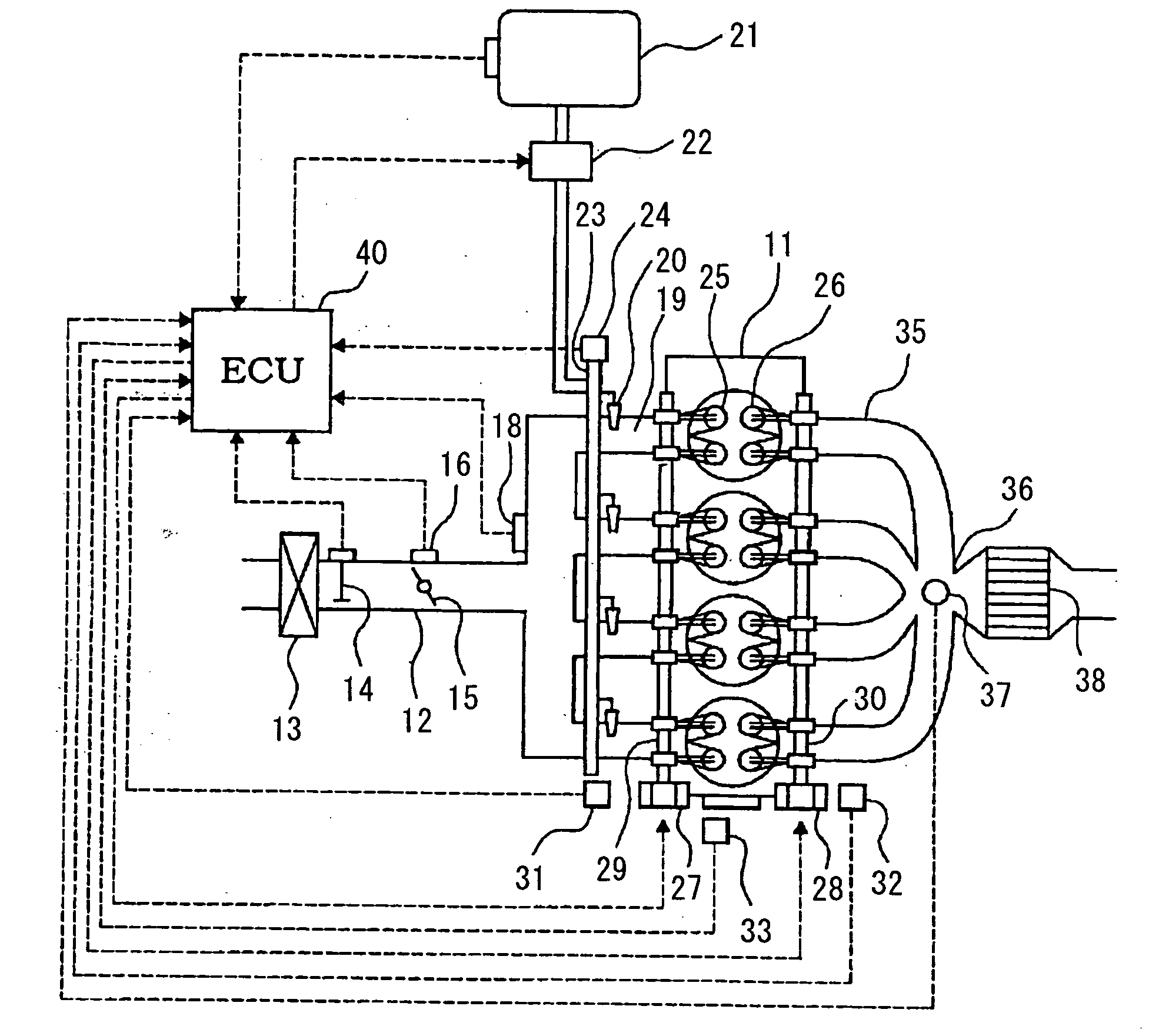
Figure 1 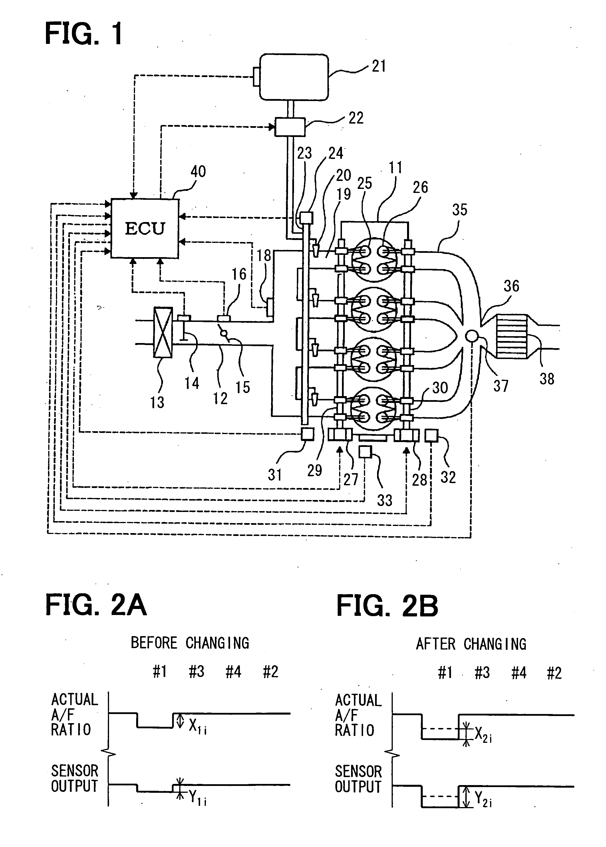
Figure 2 
Figure 3
Abstract
Description
CROSS-REFERENCE TO RELATED APPLICATION
[0001] This application is based on Japanese Patent Applications No. 2006-110366 filed on Apr. 13, 2006, No. 2006-143031 filed on May 23, 2006, and No. 2006-184135 filed on Jul. 4, 2006, the disclosures of which are incorporated herein by reference.FILED OF THE INVENTION
[0002] The present invention relates to an air-fuel ratio detection apparatus of an internal combustion engine. The apparatus detects the air-fuel ratio of exhaust gas of each cylinder on the basis of the signal of an air-fuel ratio sensor disposed in an exhaust pipe in a multi-cylinder engine.BACKGROUND OF THE INVENTION
[0003] In an exhaust emission control system of an engine, a three-way catalyst is disposed in an exhaust pipe and exhaust gas is cleaned by this three-way catalyst. When the air-fuel ratio of the exhaust gas is controlled to a stoichiometric air-fuel ratio, the three-way catalyst disposed in the exhaust pipe can efficiently clean the exhaust gas. For this reason, an...
Examples
first embodiment
[0045]A first embodiment of the present invention will be described with reference to FIG. 1 to FIG. 4. First, the general construction of an engine control system will be described with reference to FIG. 1. An air cleaner 13 is disposed in the upstream portion of an intake pipe 12 of an internal combustion engine, for example, an in-line four-cylinder engine 11. An air flow meter 14 for detecting an intake air quantity is disposed downstream of the air cleaner 13. A throttle valve 15 having its opening controlled by a motor or the like and a throttle position sensor 16 for detecting a throttle opening are disposed downstream of the air flow meter 14.
[0046]Moreover, a surge tank 17 is disposed downstream of the throttle valve 15. The surge tank 17 is provided with an intake pipe pressure sensor 18 for detecting an intake pipe pressure. The surge tank 17 is provided with an intake manifold 19 for introducing air into the respective cylinders of the engine 11. Fuel injection valves 20...
second embodiment
[0065]Next, another embodiment will be described with reference to FIG. 6. When the processing of this flow chart is performed, the presence or absence of abnormality caused by the time degradation or the clogging of injection port of the injector, the depositing of an EGR port, and the characteristic abnormalities of VVL and VVT can be detected by a computed deviation in the air-fuel ratio. The processing of this flow chart is performed at intervals of a specified crank angle.
[0066]When the processing of this flow chart is performed, it is determined in step 1031 whether it is a cylinder in which a cylinder difference is to be detected this time and whether the execution conditions of cylinder difference estimation determination are satisfied. Here, that the execution conditions of cylinder difference estimation determination are satisfied means, as described above, that the engine operating state is steady and that the air-fuel ratio sensor is active. It is recommendable to determ...
third embodiment
[0072]A third embodiment of the present invention will be described with reference to FIG. 8 to FIG. 11.
[0073]In this third embodiment, the ECU 40 estimates the air-fuel ratio of each cylinder on the basis of the detected value of the air-fuel sensor 37 by the use of a model of estimating a cylinder air-fuel ratio when the specified execution conditions of cylinder air-fuel ratio control are satisfied; the detected value being the actual air-fuel ratio of exhaust gas flowing through the exhaust gas merging section 36. Further, the ECU 40 computes a fuel correction quantity (fuel correction factor) of each cylinder according to the deviation between the estimated air-fuel ratio of each cylinder and the target air-fuel ratio. Still further, the ECU 40 corrects the fuel injection quantity of each cylinder by the use of the fuel correction quantity of each cylinder and the learned value of a cylinder air-fuel correction quantity of each cylinder, the cylinder air-fuel correction quantit...