
High pressure steam water injector comprising an axial drain
a technology of injector and axial drain, which is applied in the direction of mixer, steam boiler components, reactor fuel elements, etc., can solve the problems of difficult design of devices, insufficient performance of injector prototypes, and unreliable use of injectors in nuclear reactors
Patent Information
- Authority / Receiving Office
- US · United States
- Patent Type
- Applications(United States)
- Current Assignee / Owner
- Publication Date
- 2002-11-07
- Estimated Expiration
- Not applicable · inactive patent
Smart Images
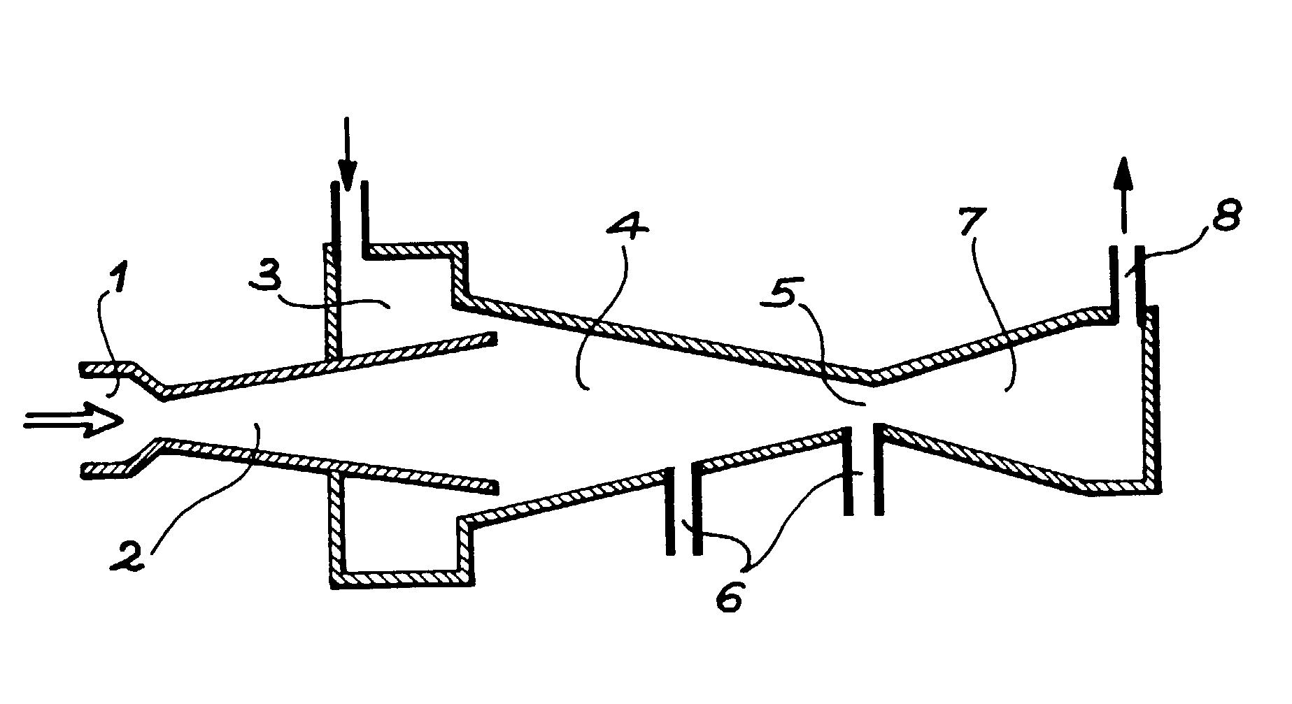
Figure 1 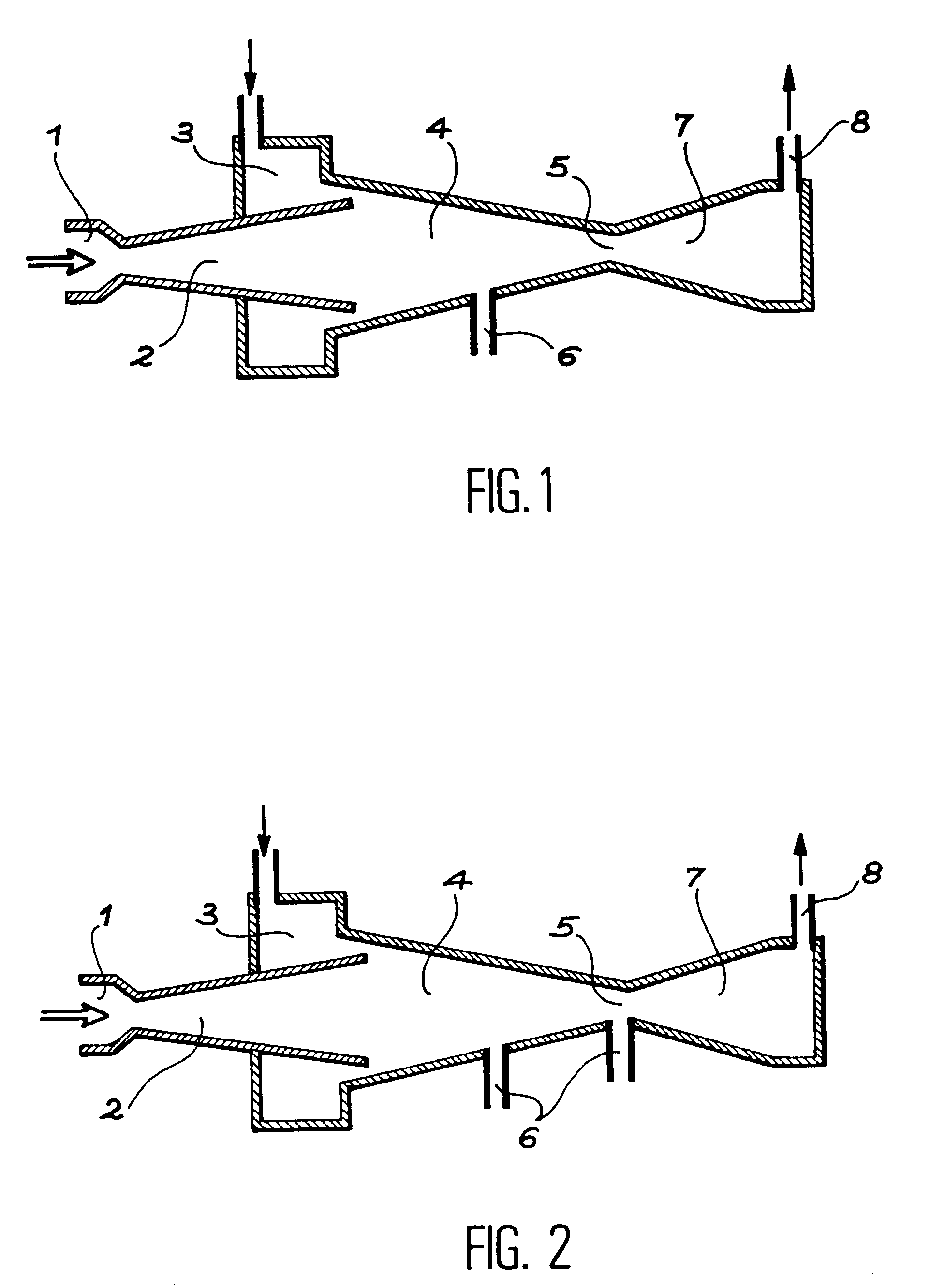
Figure 2 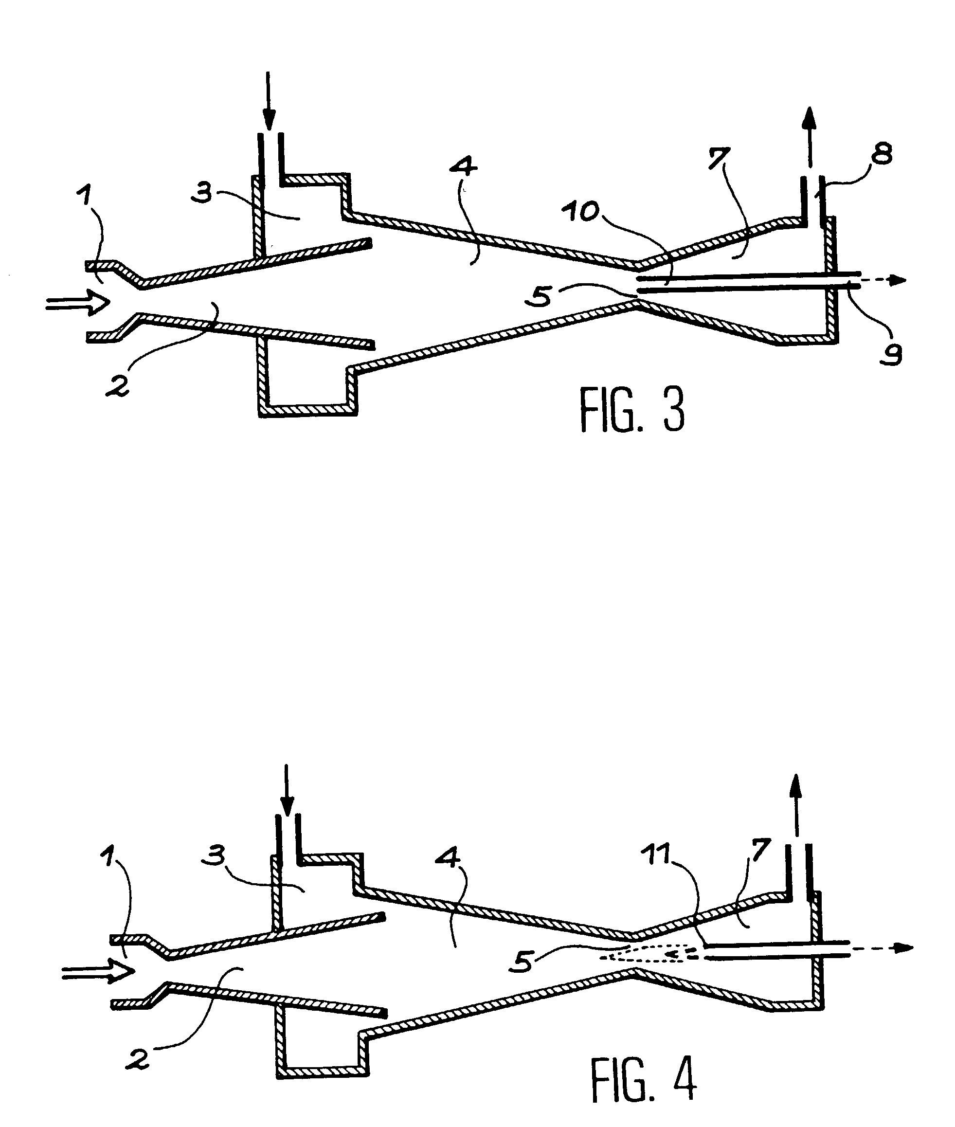
Figure 3
Abstract
Description
[0001] The invention relates to the area of high pressure injectors, intended to inject water into a machine or installation containing a pressurized reservoir. Generally, the latter is the steam production tank of a steam boiler. This is the case in particular for steam generators used in nuclear reactors, especially pressurized water reactors. However, the use of this type of injector could be applied to any type of steam-producing reservoir using part of this steam as driving energy source and a low pressure reservoir as water source.PRIOR ART AND PROBLEM RAISED
[0002] For over a century the use of steam injectors has been known (see GIFFARD patent in 1850), in particular for steam engines such as locomotives and ships. Nowadays, these devices are especially used in industrial installations requiring the decanting of solutions or liquid waste likely to rapidly deteriorate conventional pumping systems. In water nuclear reactors, the use of injectors as an emergency supply has been ...
Examples
Embodiment Construction
[0025] With reference to FIG. 3, the injector of the invention reproduces the main parts of the steam injector of the prior art described with reference to FIG. 1, with the exception of the side evacuation drain 6. There is therefore a steam inlet 1 leading into a Laval nozzle 2, a ring-shaped entry chamber 3 leading into the mixing chamber 4, positioned at the outlet of nozzle 2 and ending in neck 5. A diffuser 7 is placed at the exit of the neck leading into an outlet 8. At the neck 5, an axial drain 10 is positioned that is formed of an evacuation duct and extends across diffuser 7 and ends on the outside 9, outside the steam injector that is the subject of this application. It has been shown that diphase flow remains essentially annular as far as the neck, the film of water being flattened against the wall of this mixing chamber 4. This experimental fact contradicts previously accepted knowledge, namely the more or less rapid spraying of the aspirated film of water. Said axial d...