
Claw pole motor stator
a stator and claw technology, applied in the field of claw pole motor stators, can solve the problems of disadvantageous increase of axial dimensions of stators, large disadvantageous thickness of stator units, and difficulty for conventional motors to meet the objective of reducing the axial thickness of claw pole motors.
Patent Information
- Authority / Receiving Office
- US · United States
- Current Assignee / Owner
- Publication Date
- 2005-01-20
- Estimated Expiration
- Not applicable · inactive patent
Smart Images
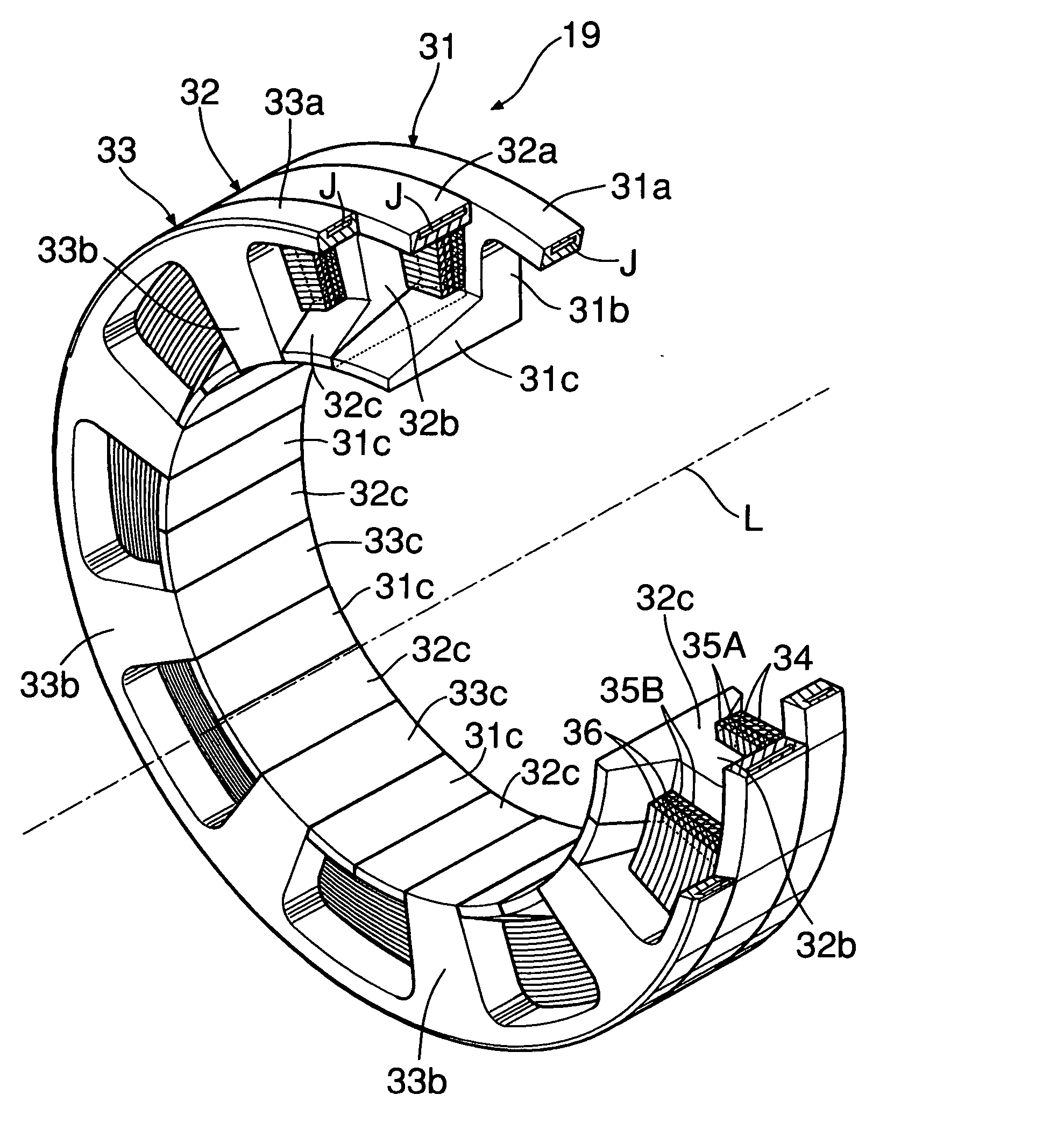
Figure 1 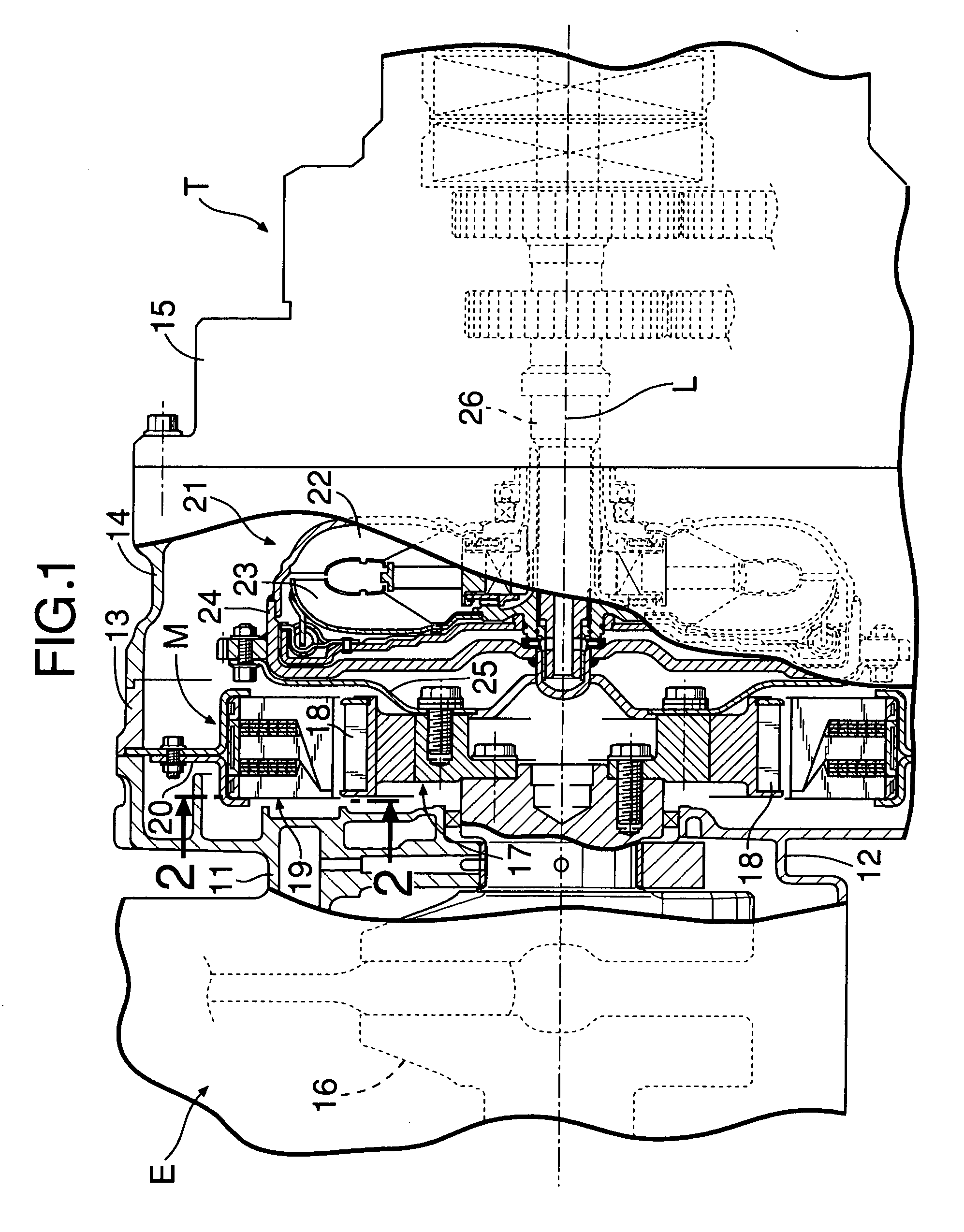
Figure 2 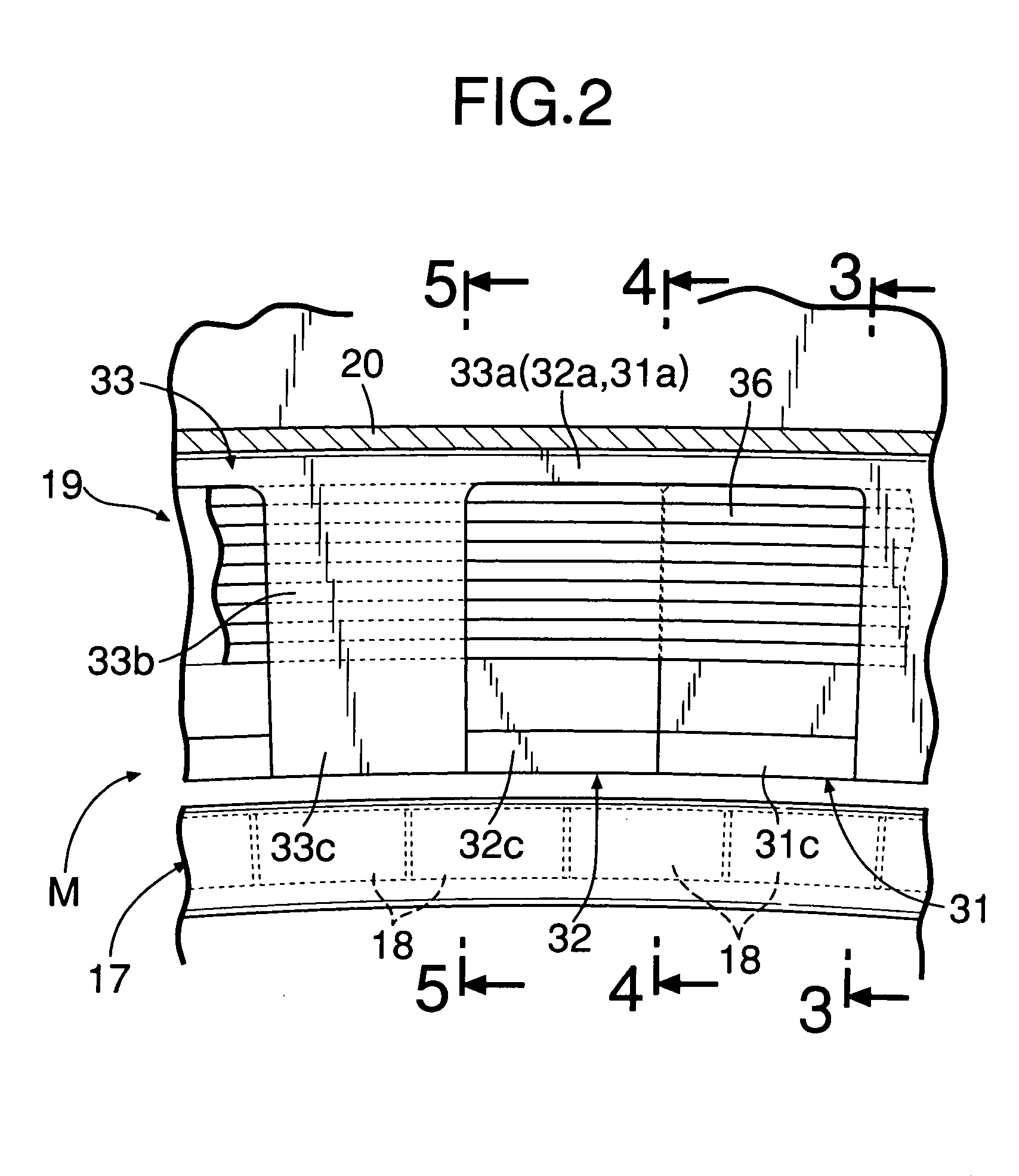
Figure 3
Abstract
Description
BACKGROUND OF THE INVENTION
[0001] 1. Field of the Invention
[0002] The present invention relates to a claw pole motor stator in which teeth for N phases juxtaposed in an axial direction have coils for N phases wound therearound within a plane perpendicular to an axis.
[0003] 2. Description of Related Art
[0004] A type of claw pole motor stator is disclosed in Japanese Patent Application Laid-open No. 7-227075. The stator is provided with three stator units that correspond to each of a U-phase, a V-phase, and a W-phase. Each stator unit is formed with a U-shaped cross-section having two sets of teeth spaced from each other in the axial direction, and a return path to connect the teeth at radially outer ends thereof. By energizing an annular coil housed within the U-shaped cross-section stator unit, an independent magnetic path is generated, which magnetizes two types of poles having different polarities. The poles are projectingly provided at radially inner ends of the two sets of t...
Examples
second embodiment
[0082] the present invention is now explained with reference to FIGS. 8A and 8B.
first embodiment
[0083] The U-phase, V-phase, and W-phase teeth 31b, 32b, and 33b, respectively, of the stator 19 of the first embodiment are arranged at different phases in the peripheral direction. Also, the poles 31c, 32c, and 33c extending in the axial L direction from the radially inner ends of the teeth 31b, 32b, and 33b have the same length as the thickness in the axial L direction of the stator 19. The width of the permanent magnets 18 of the rotor 17 is the same as the width of the poles 31c, 32c, and 33c. Additionally, the permanent magnets 18 are shared between the poles 31c, 32c, and 33c of the respective phases.
[0084] In contrast, U-phase, V-phase, and W-phase teeth 31b, 32b, and 33b of a stator 19 of the second embodiment are arranged in phase with each other. Also, poles 31c, 32c, and 33c extending radially inward from the teeth 31b, 32b, and 33b are also arranged in phase with each other. However, the permanent magnets 18 disposed on the outer periphery of a rotor 17 are arranged in ...