
Device capable of detecting vibration/shock
a technology of vibration/shock and detection device, which is applied in the direction of instruments, optical beam sources, semiconductor lasers, etc., can solve the problems of increasing steady state error of tracking error signal, affecting the magnitude of vibration/shock, and affecting the operation of the pick-up head of the optical disk driv
Patent Information
- Authority / Receiving Office
- US · United States
- Current Assignee / Owner
- Publication Date
- 2005-04-21
- Estimated Expiration
- Not applicable · inactive patent
Smart Images
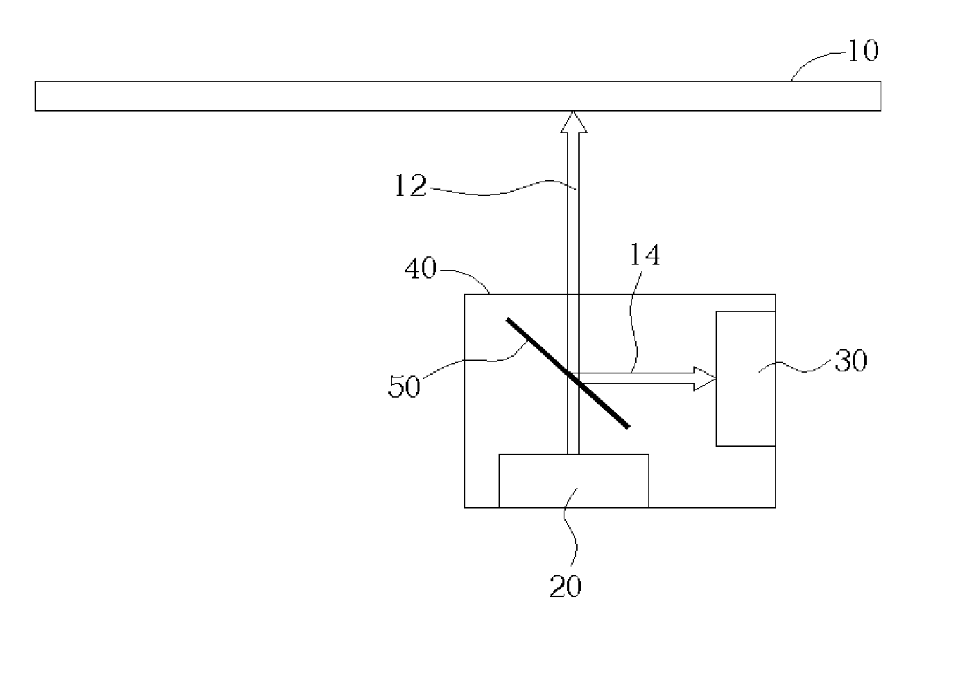
Figure 1 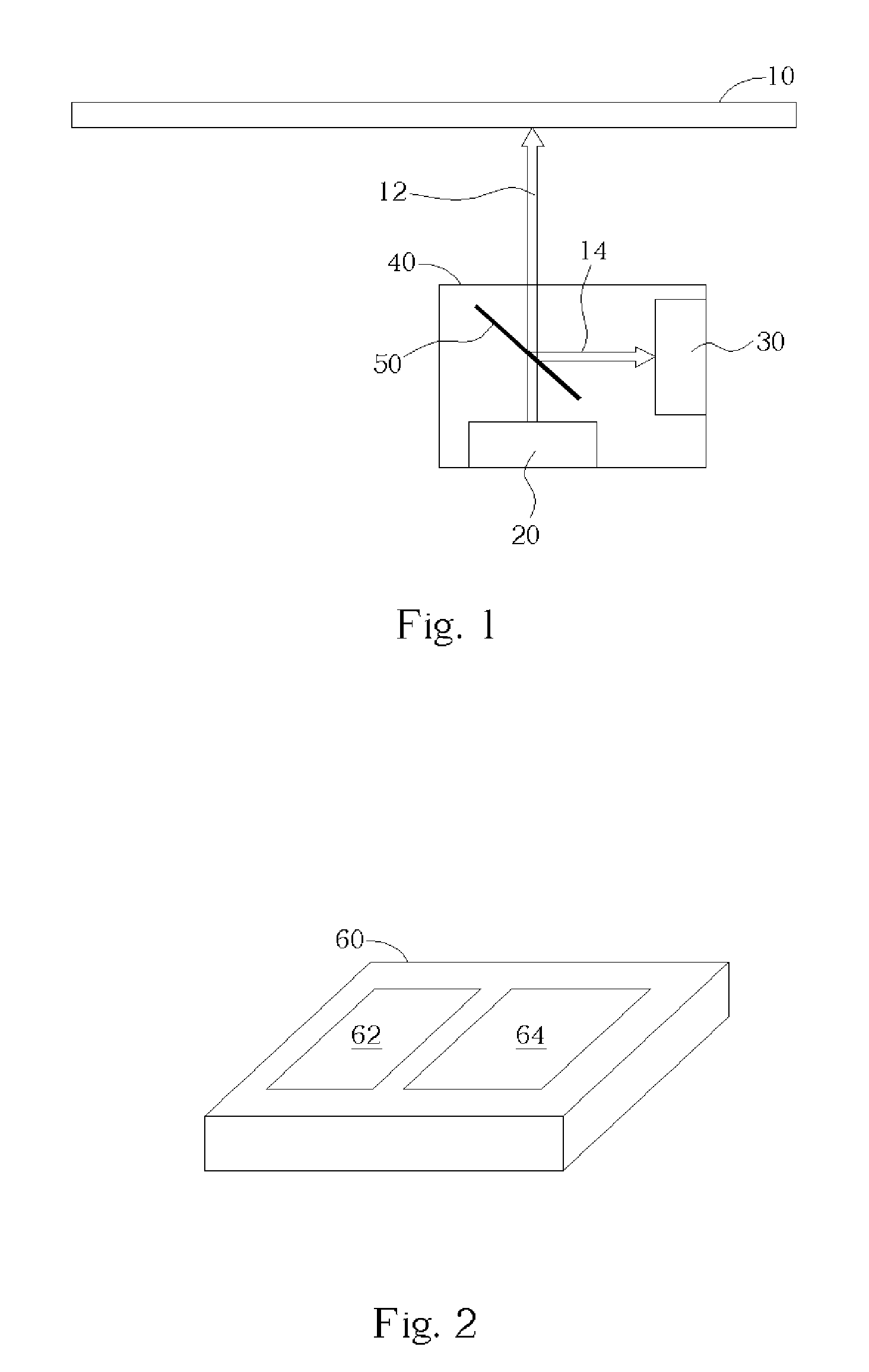
Figure 2 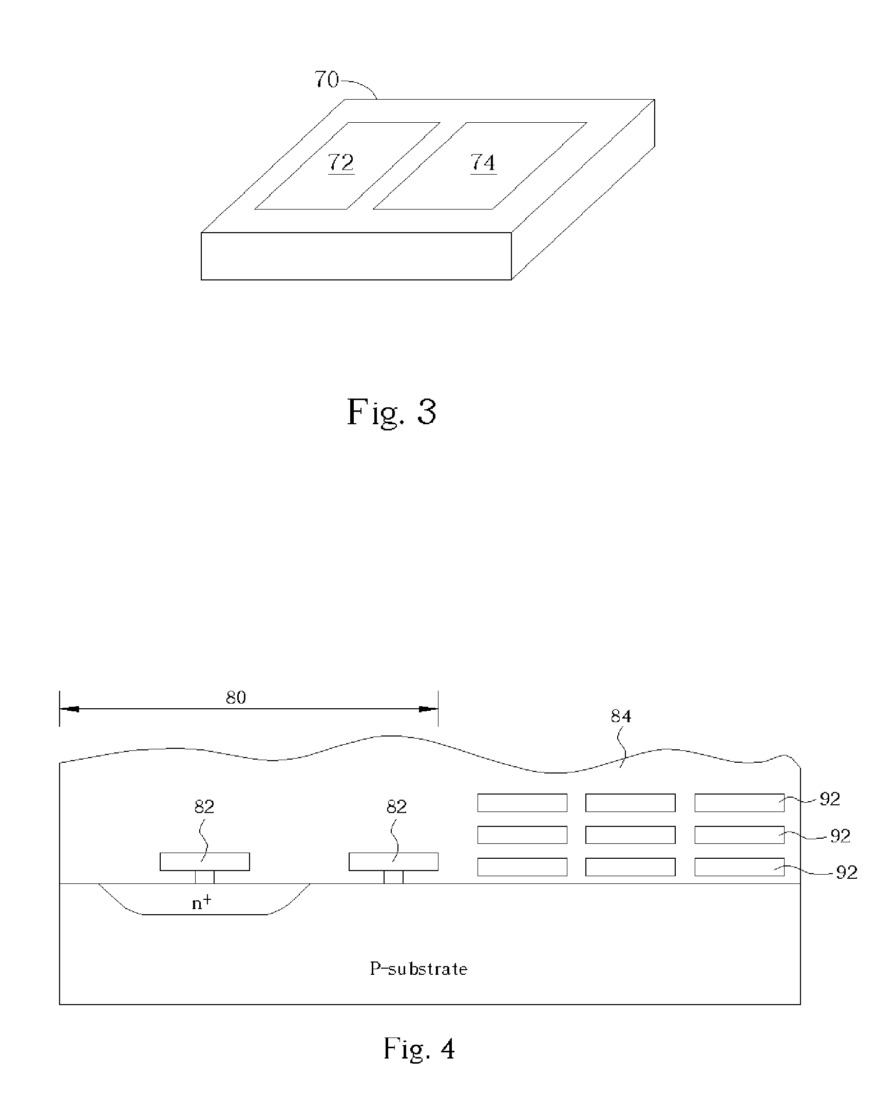
Figure 3
Abstract
Description
BACKGROUND OF INVENTION
[0001] 1. Field of the Invention
[0002] The present invention relates to a device capable of detecting vibration / shock, and more particularly, to a device capable of detecting vibration / shock integrated with a laser diode or a photo detector chip within a pick-up head.
[0003] 2. Description of the Prior Art
[0004] Generally speaking, a vibration or shock usually causes an optical disk drive to read data from a disk in error or to write data to a disk in error, and sometimes results in break down of the pick-up head of the optical disk drive and / or damage to the disk.
[0005] For protecting the optical disk drive and the disk from being damaged by vibration or shock, there must be some mechanism for detecting any significant vibration and shock in the disk drive. In an optical disk drive, the tracking error signal may be utilized to detect vibration and shock; when an optical disk drive suffers from vibration or shock, the steady state error of the tracking err...
Examples
Embodiment Construction
[0019] Please refer to FIG. 1. FIG. 1 is a diagram of the relative location between a pick-up head 40 and a disk 10. Generally, the pick-up head 40 comprises a laser diode 20, a beam splitter 50, and a photo detector 30. The laser diode 20 transmits a laser beam 12, which is focused on the disk 10 through the beam splitter 50. Further, the laser beam 14 is reflected from the disk 10 and is directed by the beam splitter 50 onto the photo detector 30.
[0020] Please refer to FIG. 2 and FIG. 3. FIG. 2 and FIG. 3 are two perspective diagrams of the present invention pick-up head capable of detecting vibration and shock. As illustrated in FIG. 2, a vibration / shock detector 64 is integrally formed on a chip 70 of a photo detector 62. In general, the vibration / shock detector 64 may be a piezoelectric detector, a piezo-resistant detector, or a capacitance detector. These categories of vibration / shock detector are capable of determining the received magnitude of vibration / shock according to s...